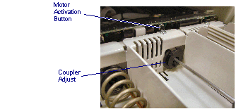
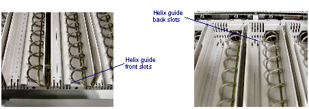
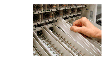
Contents
Tools you need 11
Oral Helix 23
Injectable Helix 24
Helix Positions 27
Single Helix, Single Position (SHSP) 27
Single Helix, Double Position (SHDP) 27
Double Helix, Double Position (DHDP) 27
Configuration 34
If Supplies Become Skewed 53
For Ampules 53
For Sticking Supplies 54
Package Size 56
Orientation 57
Package Condition 58
Visibility 58
Maximum weight limitations 61
Maximum Payloads for Drawer Modules 62
This manual is a guide for replenishing supplies in MedSelect Flex, SupplySelect and Centrack dispensing cabinets.
You will find information on the Unit Dose Module (UDM), the Drawer Module (DM), Compact Drawer Module (CDM), Standard Cabinet Module (SCM), and Tower Module (TM).
Use the Restock browser to restock, unload, or expire supplies in DMs, CDMs, UDMs, SCMs and cabinets/refrigerators controlled with electronic lock modules.
The return function returns unused supplies to the return drawers (special drawers in Drawer modules). The retrieve function is used to remove supplies returned by system users from retrieve drawers.
Refer to the MedSelect Display Terminal Dispensing Guide and MedSelect AWS Guide for all questions about how to use the software.
Moving Cabinets to Permanent Locations
 Qualified ABTG authorized personnel should move cabinets. If the customer chooses to move cabinets, the customer assumes all responsibility and liability for the safety of personnel and damage to cabinets.
The following must be performed before moving cabinets from staging areas to permanent stations:
If back panels were removed from the cabinet, re-install the panels. Tower modules only.
Lock doors.
Power down the equipment.
Disconnect power and IB cables from the wall. Keep appropriate cables with each cabinet.
Unplug interconnecting cables between component stacks.
Secure DT-UI.
Move levelers up (except tower modules).
Remove the temporary mount and keep it for the next set of cabinets.
Never move a cabinet to its final installation location with the temporary floor mount installed. Remove the mount and return its bolt to the bolt hole storage location on the side of the mount.
Equipment may arrive on a pallet or casters. It may be possible to wheel equipment to a permanent location and lower the leveling feet to set it in place.
When moving equipment on casters: Be aware of gaps between floors and elevators. Inclines and thresholds that require raising /lifting the equipment may require more than one person to move equipment.
This chapter provides details on the configuration and setup of the Unit Dose Module (UDM).
Overview
Once a machine is configured, no adjustments are needed for restocking and use. Adjustments should only be made when packaging or supplies change.
There are three UDM dispensing mechanisms:
Injectable dispensing bins
Solid/Oral helixes
Injectable helixes
Injectable dispensing bins cannot share a shelf with either type of helix, but solid/oral and injectable helixes can share the same shelf.
Note: The UDM should always be accessed through the Display Terminal. If manual access to the UDM is required during a power outage or other emergency, only pharmacy personnel with appropriate access privileges can access the equipment.
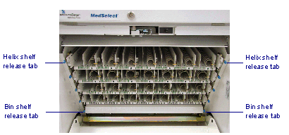
Accessing UDM Shelves
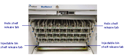
Open the front door.
Simultaneously depress the release levers on each side of the shelf assembly that latches the shelf, and guide the shelf assembly to its fully-extended position.
Accessing UDM Shelves
Injectable Bin Shelf Parts
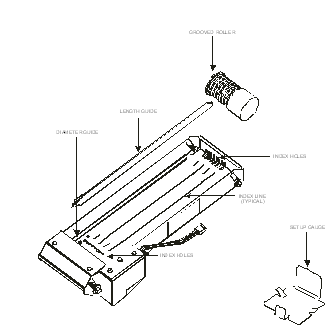
Familiarize yourself with the shelf and bin parts prior to reconfiguring an injectable bin shelf or setting up a dispensing bin.
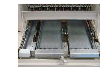
Refer to the figure below, which has the front cover raised to show the fronts of the bins.
Injectable bin shelf
The figure below illustrates the injectable bin parts.
Injectable Bin Parts
Refer to the table below for bin size and part number.
|
Bin
|
P/N
|
|
Small
|
10-501047-000A
|
|
Medium
|
10-501047-000B
|
|
Large
|
10-501047-000C
|
Injectable Bin Sizes, Configurations and Medication Sizes
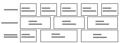
Injectable bins can only be installed on a shelf in fixed configurations. The location of a medication in a bin is identified by its bin position on the shelf.
The bin sizes and combinations that can be fitted on a shelf including the bin cable connection for each configuration is shown in Figure See Injectable Bin configurations and Connector Locations..
The dispensing bin number shown does not necessarily correspond to its connector designation on the controller location.
Injectable Bin configurations and Connector Locations
Minimum and maximum medication sizes:
|
Bin Size
|
Small
|
Medium
|
Large
|
|
Minimum medication size
|
0.35” dia. x 0.50” long (0.89cm dia. x 1.27cm long)
|
0.35” dia. x 0.50” long (0.89cm dia. x 1.27cm long)
|
0.35” dia. x 0.50” long (0.89cm dia. x 1.27cm long)
|
|
Maximum medication size
|
1.35” dia. x 2.10” long (3.4cm dia. x 5.3cm long)
|
1.35” dia. x 3.25” long (3.4cm dia. x 8.3cm long)
|
1.35” dia. x 5.75” long (3.4cm dia. x 14.1cm long)
|
Replacing an Injectable Dispensing Bin
Follow the steps below to replace a UDM injectable dispensing bin.
The injectable dispensing bins are unsecured in the shelf assembly when the assembly cover is opened. It is possible that bins could fall free of the shelf.
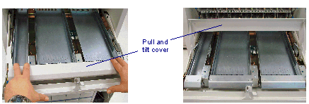
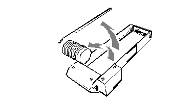
Release the spring loaded injectable bin cover at the front of the module by pulling it forward. Tilt it upward to its fully-opened position.
Accessing Injectable Bin
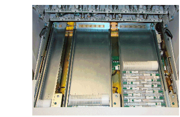
Lift the front of the bins to roll items to the back of the bin where they can be removed.
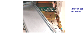
The bins rest on a lip of the shelf. A solenoid cable is attached to each bin with the mating connector located under the back of the bin. Move the bin a few inches from the shelf to access the connector. Note the connector position and remove the cable before removing the bin.
Injectable Bin Connector
Replacing an injectable dispensing bin is the reverse of removal. Be sure to reconnect the solenoid power cable in its original position. Replace the bin ensuring the cable is not pinched between the bin and the shelf lip. Replace all bin components.
Note: When replacing a left hand large bin, it may be difficult to connect the solenoid cable. If so, turn the bin clockwise or position it towards the back.
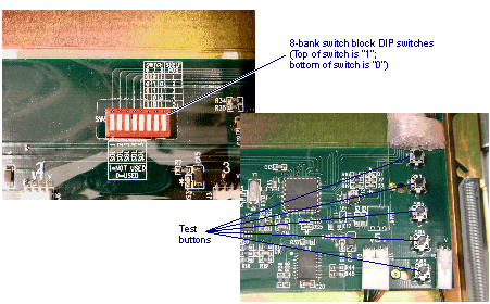
The DIP switches must be correctly set. Follow these steps to set the DIP switches:
Use the IBon/off switch to cut off IB power.
Change the DIP switches to its proper setting.
Shelf position DIP switches
The 3 right switches (6, 7, 8) identify the shelf position in the cabinet. These only need to be changed if they were changed or are new shelves. A bin shelf can be in any of the five shelf positions. A table located adjacent to the DIP switches is on the controller board to assist in setting the switches.
Bin configuration DIP Switches
The 5 left DIP switches (1, 2, 3, 4, 5) are used to identify the bin position on the shelf. A table adjacent to the DIP switches is shown on the controller board to assist in setting the switches.
c) Reconnect the IB power
DIP Switches and Test Buttons
Refer to the following procedure for setting up an injectable dispensing bin.
Use the test buttons to verify bin function.
If necessary, reconfigure positions at the AWS.
Procedure for Setting up an Injectables Dispensing Bin
Tools you need
The correct (small, medium, or large) injectable bin setup gauge.
5/16-inch nut driver
Enough medication to fill the bin for testing
Electronic access to Unit Dose Module
The bin setup gauge and nut driver are included in the Unit Dose Module setup kit (P/N 10-501339-000A).
Note: The setup kit is not supplied with the UDM. Kits are ordered by the customer based on the quantity of modules at the site and their proximity to each other, i.e., two modules next to each other may require only one kit.
To set up an injectables dispensing bin:
Pull out the shelf that contains the bin you want to set up. Refer to Figure See Accessing UDM Shelves..
Lift the shelf cover.
Note which connector on the circuit board is connected to the bin you want to remove. Refer to Figures See Injectable Bin Connector. and See DIP Switches and Test Buttons..
You may have to lift this bin or other bins out of the shelf to see the connectors. Connectors are labeled 1, 2, 3, 4 and 5.
Remove the dispensing bin from the shelf.
Remove all medications, roller, and the plastic length guide, if present.
The length guide is removed by pulling up the front until it unsnaps, and then lifting the back out of the bin.
Remove Meds and Components
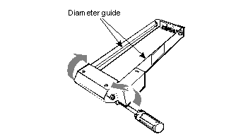
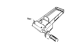
Using the nut driver, loosen (1/2 to 1 turn) the two front hex head adjusting screws as shown.
This loosens the diameter guide, which includes the two silver rails that run along the inside walls of the bin.
Loosen Diameter Guide
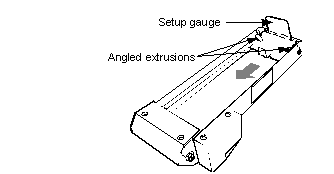
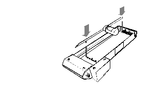
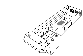
There are three bin sizes: small, medium, and large. Use the proper size setup gauge. Insert the setup gauge into the rear of the bin and slide it forward along the rails of the diameter guide until it stops at the dispensing end.
The figure below shows how to place a small setup gauge into a small bin.
Note: Ensure the angled extrusions are above the diameter guide.
Insert Setup Gauge
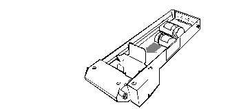
Lift the diameter guide just enough to fit the medication and slide in enough to fill the area underneath the gauge. (The first medication should be placed with its base to the right.) Alternate the direction of the medication as shown below. Be sure the gauge is oriented in the bin as shown.
Medications Under Gauge
Push the base of each medication flush against the side it is facing as shown above. This method of arranging medications ensures the adjustment gauge rests evenly on the medications, especially if a container is wider at one end. Alternating may be necessary for setup only; it may not be appropriate to alternate when loading the bin for actual use. For loading medications, see Loading an Injectables Bin in chapter 6.
Note: Do not allow the medications to roll out from under the set up gauge. When placing medications into the bin, block the dispensing end or otherwise safeguard the items from falling through the dispensing gate. Some medications can break when dropped.
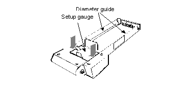
Lower the diameter guide until the gauge comes in contact with the medications as shown below. Lightly press with your fingers.
Lower Diameter Guide
Lightly work the diameter guide up and down to remove any gap between the sides of the gauge and the medications. Do not force the diameter guide down so it deforms the medications.
Tighten the two front screws until they hold the diameter guide in place.
Tighten Diameter Guide
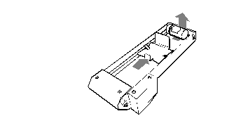
Remove the medications and setup gauge from the dispensing bin. Slide the gauge to the rear of the bin and lifting it out. It may be necessary to slide the gauge towards the rear to loosen the medications under the gauge.
Remove Meds and Setup Gauge
Determine if a length guide is needed. The guide contains the left side of shorter medications that don’t fill the bin. Place a medication into the bin at the rear, with its base flush against the right side. Slots are provided for installing one end of the length guide. If no slots are exposed, a guide is not needed. Do not force a guide in place.
If a guide is needed, insert the rear tab into the slot next to the end of the medication. Install the pin on the front into the hole that sets the guide parallel with the sides of the bin. Use the round index holes and index lines to count and align the front and rear of the length guide.
Insert Length Guide
If the diameter guide is in the lowest position, the length guide can be inserted as follows:
Place the rear tab of the length guide in the correct slot in the rear of the bin.
Move the front of the length guide to the right side of the bin keeping the rear tab in its slot.
Twist the front of the length guide so it fits under the diameter guide.
Keeping the length guide twisted, and its rear tab in its slot, move the front of the length guide to its correct location.
Place a medication in the bin and check that it rolls freely in the bin. If it does not, return to Step See Insert Setup Gauge. and repeat this procedure.
Fill the bin with medications. Be sure to leave enough room after the last medication for placing the roller. For instructions on properly loading a bin, see Loading an injectables Bin in chapter 6.
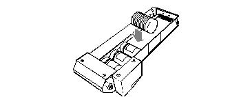
Insert the roller. Be certain it moves freely in the bin. Rollers are inserted with the ungrooved side on the right as shown.
Replace Meds and Roller
If desired, mark the right rail of diameter guide with a pencil to facilitate counting meds during restocking. Make tick marks to indicate the actual med count. Consider ticks at 5 or 10 counts of meds. Do not use ink because med counts may change depending on container size.
Helix Shelf Components
There are two types of helix shelves: oral helix shelves for dispensing solids/oral packages and injectable helix shelves for dispensing ampules and vials.
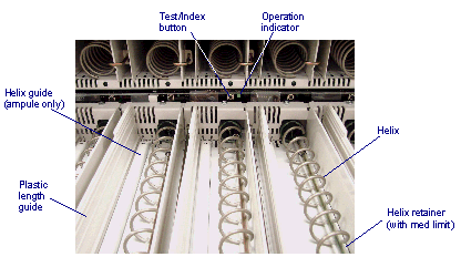
All single shelf rows use a helix, helix retainer, and length guide.
The parts of a helix dispensing position are shown in the figure below. Not all parts are required for each medication type. Refer to the See Helix Chart..
Helix Shelf Components
After any shelf is configured, press the test button to ensure that the helix rotates and indexes properly with no flex, wobble or distortion.
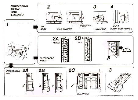
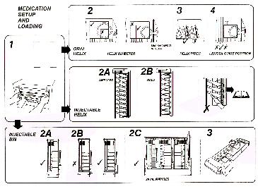
UDM Medication Setup and Loading
This graphic, which is on the inside of the UDM cover, displays the correct and incorrect ways to load a UDM. Use this and the instructions in this chapter to determine how to properly configure oral and injectable helixes and injectable bins.
Medication Setup and Loading
Helix Chart
Use this table to determine the proper helix and components for the type of medication being used.
|
Helix
|
P/N
|
Med Type
|
Capacity 40
|
Capacity30
|
Capacity20
|
Capacity15
|
Retainer
|
Med Limit (2 sizes)
|
Helix Guide
|
Length Guide
|
|
Oral helix 1x40
|
10-501031-000A
|
oral
|
X
|
|
|
|
X
|
|
|
X
|
|
Oral helix 1x30
|
10-501031-000B
|
oral
|
|
X
|
|
|
X
|
|
|
X
|
|
Oral helix 1x20
|
10-501031-000C
|
oral
|
|
|
X
|
|
X
|
|
|
X
|
|
Oral helix 1.4x40
|
10-501031-000D
|
oral
|
X
|
|
|
|
X
|
|
|
X
|
|
Oral helix 1.4x30
|
10-501031-000E
|
oral
|
|
X
|
|
|
X
|
|
|
X
|
|
Oral helix 1.4x20
|
10-501031-000F
|
oral
|
|
|
X
|
|
X
|
|
|
X
|
|
Injectable helix A
|
10-501042-000A
|
1, 2 mL ampule 1, 2, 3 mL vial
|
|
|
X
|
|
X
|
X
|
X (ampule only)
|
X
|
|
Injectable helix B
|
10-501042-000B
|
5 mL ampule 5 mL vial oral
|
|
|
|
X
|
X
|
|
X (ampule only)
|
X
|
Configurations by Medication Type
Oral Helix
To set up an oral medication position:
The medication package must have a minimum of 50% of its width inside the helix but the package cannot be so small that it doesn’t extend past the outer edge of the helix.
Choose a helix capacity and pitch that is as small as possible for the medication to fit but not too tight in the helix.
Place the length guide as close to the medication as possible without being too tight.
For medications that are too wide to be placed in a single helix, refer to See Helix Positions..
Injectable Helix
For small (1, 2, 3 mL) ampules/vials:
Use a 20 capacity helix with med limits.
For medium (5, 6 mL) ampules/vials:
Use a 15 capacity helix without med limits.
For all ampules/vials:
Place the length guide in the left-most position for ampules and as close as possible to the vials without being too tight.
Injectable Helix
Helix Sizes and Identification
The solids/orals helix shelves are used for dispensing solids/orals medication packages. The injectable helix shelves are used for dispensing ampules/vials. Each capacity is color coded on the coupler end except the 15 capacity, which has no color code.
Helixes are available in various pitches that provide 15, 20, 30, and 40 medication capacities for oral packages with different thickness. For different package heights and widths in sizes, two different helixes of 1" (2.54 cm) and 1.4" (3.6 cm) outside diameters are available. Pitches of 15 and 20 are for different volume ampules/vials.
Refer to Loading a Solids/Orals Helix Dispensing Position in chapter 6 for additional guidelines. Refer to the table below for helix colors/identification.
|
|
Right/Clockwise Turning
|
Left/Counter-Clockwise Turning
|
|
Capacity
|
15
|
20
|
30
|
40
|
20
|
30
|
40
|
|
Diameter 1.0
|
No color
|
Green
|
Yellow
|
Black
|
--
|
--
|
--
|
|
1.0 pitch
|
0.91
|
0.75
|
0.51
|
0.39
|
--
|
--
|
--
|
|
Diameter 1.4
|
--
|
Green
|
Yellow
|
Black
|
Green
|
Yellow
|
Black
|
|
1.4 pitch
|
--
|
0.75
|
0.51
|
0.39
|
0.75
|
0.51
|
0.39
|
Helix Positions
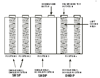
An oral helix shelf may have up to seven dispensing positions. Single helixes can be used to dispense most medications. Adjacent helix positions can be combined to dispense medications too wide for single position helixes.
When choosing an oral helix type, see Loading Medications, chapter 6.
Note: Injectable helix and solids/orals helix dispensing positions can be combined on a single helix shelf.
Single Helix, Single Position (SHSP)
This is the standard, one motor configuration. Seven single helixes can fit on one oral helix shelf.
Single Helix, Double Position (SHDP)
This motor configuration supports drugs that are too wide to fit into a single helix position, but are not so wide as to require two helixes.
Double Helix, Double Position (DHDP)
This motor configuration supports drugs that are too wide to be placed in a single helix.
The first helix dispensing position on the left is always position 1 on that shelf, regardless of its configuration. Each position to the right is then numbered consecutively, regardless of the configurations. Position numbers and all three helix configurations are shown in the graphic on the following page.
Helix Positions
Combining Adjacent Oral Helix Dispensing Positions for DHDP
An adjacent permanent divider must be removed to combine positions. The rotation of the motor on the left-hand side must be reversed and the helix changed to rotate counter-clockwise. All combined positions use the 1.4” diameter helixes.
An ABTG-sanctioned technician must perform this procedure.
Replacing a Different Capacity, Same Diameter Helix
Refer to the See Helix Chart. and See Configurations by Medication Type..
Extend the shelf assembly - refer to Accessing UDM Shelves, Figure See Accessing UDM Shelves..
Empty any medications from that position.
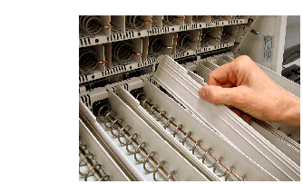
Remove the length guide from the bin by lifting it from the rear first.
Remove Length Guide
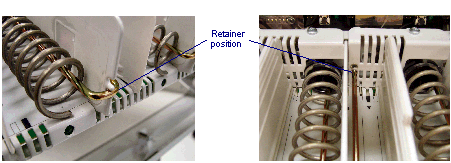
Note if the helix retainer position is in the upper (1.4” helix) or lower (1.0” helix) slot and hole.
Helix Retainer Position
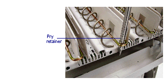
Use a screwdriver or similar tool to pry the helix retainer (and med limit, if equipped) out of the hole and remove the retainer from the helix.
Remove Helix Retainer
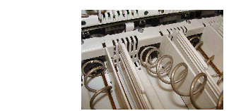
Lift the helix from the dispensing end to disengage the helix from the coupler.
Remove Helix
Remove the helix from the position.
Place the new helix in the coupler. Be certain that the end of the helix fits between the notches on the coupler.
Push the retainer firmly into its original hole and slot (use the upper for a 1.4" helix, and the lower for a 1" helix).
Replace the length guide so it prevents medications from sliding side-to-side, but does not place pressure against the side of the med. The med must be able to advance freely as the helix turns, without falling out of the helix.
Use the rectangular markings on the bottom of the shelf to align the length guide in the proper holes. These markings alternate between filled and unfilled to help identify and align the holes.
If needed, reconfigure the position at the AWS.
Injectable Helix Sizes and Medication Sizes
Injectable helix dispensing shelves are used to accept vials and ampules (from 1mL to 5mL).
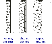
Configuration
The helix shelf configurations are described below.
|
Med Package
|
Shelf Positions Used
|
Capacity
|
Illustration
|
|
1mL, 2mL, or 3mL vials
or
1mL or 2mL ampules
5mL vials
|
1
1
|
20
15
|

|
Changing from Ampules to Vials
Refer to the See Helix Chart. and See Configurations by Medication Type..
Remove all ampules from the position you want to set up.
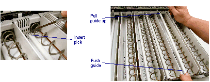
Remove the helix guide by pushing forward on the front of the guide and inserting a pick into the hole at the rear and pulling up.
Remove Helix Retainer
Adjusting a Length Guide for a Helix
Perform the following procedure to change the position of the length guide so medications fit more tightly or loosely into the space between the helix coil and the wall of the length guide. This is only for positions that store 1mL, 2mL, 3mL, or 5mL vials.
Follow steps 1 and 2 in See Replacing an Injectable Dispensing Bin..
Remove all medication from the position you want to set up.
Remove the length guide from the bin by lifting it from the rear first. move it into a new position and test the adjustment by placing a few medications into the helix.
Adjust Length Guide for a Helix
Checking and Changing the Med Limit in an Injectable Helix Dispensing Position
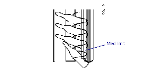
Ampules with small diameters (1mL and 2 mL) can slip through the first helix loop as shown below.
Check this by trying to press the ampule through the first helix loop (do not force it). If it slips through, use the large diameter med limit (black marking). If the ampules are too tight to allow the helix to turn freely use the small diameter med limit.
Remove all medications from the position you want to set up.
The helix retainer is positioned through the lower guide holes. Remove the retainer from the helix. Perform steps 1-5 in See Replacing a Different Capacity, Same Diameter Helix..
Slide the med limit off of the retainer and replace it with the appropriate med limit.
Slide the helix retainer and med limit back through the helix and guide hole using the lower guide hole that was originally used before you removed the retainer. The helix retainer should snap firmly into place.
This chapter provides details on the configuration and setup of the MedSelect Standard Cabinet Module (SCM).
The SCM contains movable shelves that can be raised or lowered as needed to accommodate different package sizes.
Shelves can also be divided into compartments so that different items may be stored on the same shelf.
Note: The SCM should always be accessed through the Display Terminal. If manual access to the SCM is required during a power outage or other emergency, please have the proper pharmacy personnel access the equipment.
SCM Configuration Options
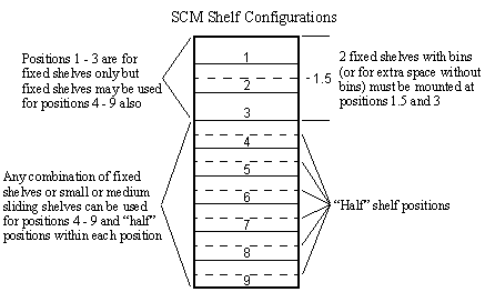
The following shelves can be configured within the nine available SCM positions:
|
Shelf
|
Size
|
Positions Required
|
|
Small (Sliding)
|
20” W x 24.5” D x 3.1” H
(50.8cm x 62.2cm x 7.9cm)
|
1
|
|
Medium (Sliding)
|
20” W x 24.5” D x 6.4” H
(50.8cm x 62.2cm x 16.3cm)
|
2
|
|
Fixed
|
21” W x 26” D x 1” H
(53.3cm x 66cm x 2.5cm)
|
1 (Can be located at half-position points)
|
When selecting a shelf position, consider ease of reaching supplies and frequency of use.
Moving the SCM Shelves
The shelves in a Standard Cabinet Module may be raised or lowered without the use of tools. There are two types of shelves: sliding or fixed. Sliding shelves slide in and out of the cabinet; fixed shelves do not.
Follow the steps below to move a sliding shelf.
Pull the shelf out until it is fully extended.
SCM Sliding Drawer in Full Extension
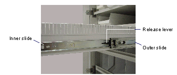
Press down on the right slide release lever and up on the left slide release lever and continue to pull the shelf out until it is free of the cabinet.
To remove the outer slide, tilt the bottom of the slide away from the cabinet, then lift the slide up and away from the cabinet.
Insert the outer slides in the new location.
Fit the inner slide back into the outer slide, and slide the shelf back into the cabinet.
Follow the steps below to move a fixed shelf.
Remove medications or supplies from the shelf.
Lift the shelf out of the cabinet.
Move the four mounting clips (used to support the shelf) to a new location.
Place the shelf in its new location.
Note: Shelves and compartments on shelves can be configured in the MedSelect software so each supply position is recognized. Do not add, remove, or modify shelf order in an SCM without the authorization of the system administrator.
Adding and Removing SCM Sliding Shelf Dividers
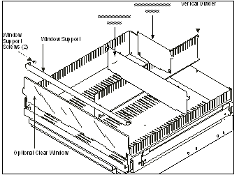
Sliding shelves may be divided into compartments with metal dividers. There are two types of dividers:
Vertical dividers run from the front to the back of the shelf.
Horizontal dividers run from the left to right sides of the shelf.
Vertical dividers are secured to the base of the shelf with sheet metal screws. Insert the divider at an angle, slide it into the rear groove and straighten.
Horizontal dividers then clip into the walls of the shelf or to a vertical divider.
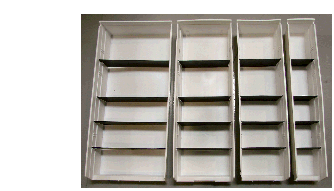
There is an optional clear window that may be used at the front of the shelf to help contain supplies. A metal window support, secured at each end by a screw, holds the window in place.
Window and divider orientation is shown in the following graphic.
Pull horizontal dividers up to remove. Remove the screws to detach the vertical divider from the base.
Fixed shelves can be divided into vertical compartments with clips. Also, clips can be attached to the shelf to keep supplies contained.
There are four bin sizes and they all can use horizontal dividers. Place clips behind the bins to properly locate them.
If additional dividers or clips are needed, contact a ABTG sales representative.
Note: Shelf compartments can be configured in the MedSelect System software so that each compartment is recognized as an individual supply position. Do not divide shelves into new compartments without the authorization of the system administrator.
This chapter provides details on the configuration and setup of the MedSelect Drawer Module (DM) and Compact Drawer Module (CDM).
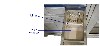
Most drawers in Drawer Modules can be divided into compartments. To do this, a plastic liner is placed into the drawer. The liner is slotted for dividers. Dividers slide in and out of the liner without tools, and can be configured to allow for a variety of different supply shapes and sizes.
Note: Drawer compartments can be configured in the MedSelect software so each compartment can be an individual supply position. Do not divide drawers into new compartments without the authorization of the system administrator.
Note: DMs and CDMs should always be accessed through the Display Terminal. If manual access is required, have the proper pharmacy personnel access the equipment by using the keys to open the drawers.
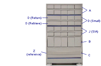
The DM module shown below identifies the drawers. A CDM allows fewer drawers to be used. The Z is a front cover (no drawer) and can be used anywhere.
Note:J drawers are small Single Item Access drawers.
Remove/Replace the Drawers
Release the drawer and pull it out of the cabinet.
Press the release lever on the bottom of the drawer to the side and remove it from the rail.
To replace the drawer, place it onto the rail and slide it into the cabinet.
Drawer Module (DM) Configuration and Compact Drawer Module Configuration Options
Any five of the following drawer assemblies can be configured into the DM. Any two of the following drawer assemblies can be configured into the CDM.
|
A Drawer Assembly
|
10 small drawers
|
|
B Drawer Assembly
|
5 medium drawers
|
|
C Drawer Assembly
|
1 large drawer
|
|
D Drawer Assembly
|
1 return, 1 retrieve and 6 small drawers
|
|
J Drawer Assembly
|
10 small single item access drawers
|
|
Z Front Cover
|
Cover only - no drawer - can be used anywhere
|
These tables describe the DM configuration options.
|
Drawer Liner
|
Size
|
|
Small (A drawers)
|
3.9” W x 20.7” D x 1.8” H
(9.9cm x 52.6cm x 4.6cm)
|
|
Medium (B drawer)
|
3.9” W x 20.7” D x 5.15” H
(9.9cm x 52.6cm x 13.1cm)
|
|
Large (C drawer)
|
17.0” W x 18.4” D x 4.8” H
(43.2cm x 46.7cm x 12.2cm)
|
|
Small (D drawer)
|
3.9” W x 20.7” D x 1.8” H
(9.9cm x 52.6cm x 4.6cm)
|
|
Small SIA (J drawer)
|
3.1” W x 18.1” D x 1.75” H
(9.9cm x 52.6cm x 4.6cm)
|
Single Item Access Drawer Configurations
SIA drawers are divided into compartments. Slide a plastic liner (flange up) into the drawer. The belt is has windows for either all small (6) or all large (3) compartments.
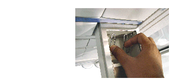
In some cases, a medication clip is used to hold packages down in the compartment. Squeeze the clip together to release it from the drawer and install it in the drawer.
This chapter describes how to load medications into the UDM, SCM, and DM.
Loading a Unit Dose Module
The instructions that follow explain how to properly load injectable and solid/oral dispensing positions.
General notes:
Ensure your counts are accurate
Check for broken, damaged, or expired meds
Check for skipped or double-loaded positions
Follow these guidelines and the decal illustration located on the inside of the UDM door (see Figure See Medication Setup and Loading.).
Medication Setup and Loading
Maximum Payload for a Unit Dose Module
The UDM has a payload limit which must not be exceeded. Payloads in excess of the specified maximum may cause personal injury or damage to the equipment.
Observe these maximum weight limitations:
The maximum payload for each shelf in the UDM is 10.4 lbs. (4.7 kg). The maximum payload for the entire UDM is 249 lbs (113 kg).
Opening a Shelf in a Unit Dose Module
Open the shelf you want to restock by pressing downward on the two blue-tipped levers on each end of the shelf. Slide the shelf out using both hands until it is fully extended.
To reduce the risk of personal injury, do not allow the shelf to fall open under its own weight. This may damage ampules, vials, and other medication contained on the shelf. Slide the shelf forward.
UDM Shelves
Loading an Injectables Bin
Refer to the table below.
|
Minimum injectable bin medication size
|
.35” diameter x .50” long (all bins)
|
|
Maximum injectable bin medication size
|
1.35” diameter x 2.10” long (small bin)
1.35” diameter x 3.25” long (medium bin)
1.35” diameter x 5.75: long (large bin)
|
Follow these steps.
Remove the roller from the bin.
Restock the desired bin with new supplies by placing each new supply into the back of the bin and letting it roll forward.
Loading Injectable Bin (1)
Generally, meds should be placed in a bin with the base of the container against the right wall of the bin as shown in the previous picture and in diagram A which follows.
Loading Injectable Bin (2)
There are three exceptions to this rule:
If Supplies Become Skewed
If the supplies become skewed with the bases in the same orientation as shown in example B which follows, alternate them as shown in example C. This is usually necessary with containers that are wider at one end than the other.
For Ampules
For 20 ml ampules, the base of the container should be against the wall that is closest to the center of the shelf as shown in example D.
For Sticking Supplies
If supply labels stick to each other, alternate their positioning as shown below (2 mL cartridges placed alternately in a medium size bin).
Loading Injectable Bin (3)
Follow these steps to position supplies.
Replace the roller behind the last medication in the bin. If a length guide is used in the bin, be sure the grooved roller moves freely in the bin, without sticking on the length guide or bin wall.
Using the Restock browser on the DT, enter the quantity of supplies added to the bins. For instructions on the Restock browser, refer to the MedSelect Display Terminal Dispensing Guide.
When you are finished loading the bins on a shelf, slide the shelf into the cabinet until it clicks into place. Pull on the shelf to make sure it is locked in.
When you are finished loading a cabinet, close the front cover and make certain it is secure.
Note: Some manufacturer's labels for small volume medications (5ml or less) can peel off the container. This may cause two containers to stick together, which prevents the medication from being dispensed. If you experience this problem, do one or both of the following:
“Contact the medication supplier to identify the problem to them.
Consider using an injectable helix rather than an injectable bin. Injectable helixes do not permit the medications to come in contact with each other so sticking is not a problem. For more information about this solution, contact an ABTG sales representative.
Loading a Solids/Orals Helix Dispensing Position
A solids/orals dispensing position can hold a large variety of supplies, and these can be placed in several different orientations. There is more than one correct way to load a helix; the following guidelines help to avoid dispensing problems and irregularities. Follow these guidelines and the decal illustration located on the inside of the UDM door (see Figure See Medication Setup and Loading.).
Package Size
Medication packages should fit loosely in the helix. If they are jammed in, they do not dispense properly. However, if a med is too loose, double loading can occur or meds can slip out.
This dispensing method is best for medications of the same type that are similar in size. Excessive variations in package size may cause unreliable dispensing.
Trimming of packages is recommended if there are excessive variations in the package sizes. If trimming is necessary because of non-symmetric packaging, keep the package sizes consistent. Ends of rolls should be the same size as the inner packages.
Double dispenses are caused by packages that do not fit correctly in a helix. The package is either too big or too small.
The maximum package height must not extend above the top of the length guide.
Orientation
When restocking, keep the package orientation in the helix consistent. It is easier to count medications and verify positions and it lets medications move on the helix smoothly.
No more than 50% of the medication width should extend past the left side of the helix.
For unbalanced medications that have the pill at one end of the package, do not stand the package with the pill at the top. It could be top heavy and may become displaced during a dispense or while closing or opening the shelf. Place the pill to the right and down for best results.
Folding medication packages to fit the dispenser is not recommended. These meds tend to spring back, which can cause them to stick or wedge in the helix, or to pop out of the helix. If folded packages are used, the material should hold a fold without springing open. Consider using tape to prevent spring.
Most medications travel to the front drop area better when loaded on the shelf floor as opposed to sitting on the helix wire.
In general, blister protrusions should face backward and not sit above the helix. However, if the blister size is similar to the inside diameter of the helix, the package may fit too tightly when the blister is facing forward. In this case, try loading the medication with the label side towards the front of the machine.
Place suppositories so they ride on the shelf (not the coil) in the cell or on the shelf in the cell behind it. Do not place them on the shelf before the cell, since they could fall through.
Package Condition
Some after-market packaging systems use an adhesive label on the back side of the formed blisters. Care must be taken to make sure that the adhesive is not exposed (e.g., at corners and edges) after the packages are separated.
Take care when separating oral med sheets. Packages with torn edges may be used if the damage is not severe. Place slightly damaged packages in the first helix position. Severe damage results in edges that catch on the helix. Don’t use badly damaged packages.
When reloading, check expiration dates so expired meds can be removed.
If corners are bent, the package should be flattened as much as possible. Otherwise the packages should be loaded with the point facing front.
For suppositories, do not bend the ends/corners.
Visibility
Consider loading meds from back to front if it improves visibility. Make sure to load oldest meds in front.
Check for double-loaded or skipped positions.
Loading an Injectable Helix Dispensing Position
An injectable helix dispensing position can hold a large variety of different-sized ampules and vials. Follow these guidelines and the decal illustration located on the inside of the UDM door (see Figure See Medication Setup and Loading.). To change an injectable helix dispensing position, see chapter 2, UDM Configuration and Setup.
When placing medications into helixes, the following statements are always true:
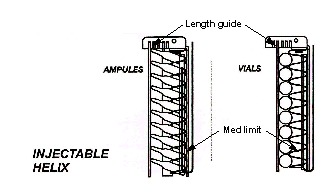
Ampules always use a helix guide.
Vials do not require a helix guide.
Always place vials into position with the base of the container down. Never place a vial into a position upside-down.
Ampules with small body diameters (1ml-2ml sizes) can slip through the first helix loop. Check this by trying to press the first ampule through the first helix loop. Do not force enough to break the ampoule or damage the helix. If the ampoule slips through the loop, change the size of the med limit. See Checking and Changing the Med Limit in an Injectable Helix Dispensing Position in chapter 2.
The following graphic shows the proper orientation of vials and ampules in helixes.
Loading Supply Cabinet Modules
When you restock an SCM, the door opens automatically. There is more than one correct way to load an SCM; however, the following guidelines will help to avoid dispensing problems:
When filling shelves or compartments within shelves, do not stack supplies above the height of the shelf or divider walls. This may result in the shelf or the shelf above it to jam when opened. Supplies may be damaged by friction caused by items rubbing against other sliding shelves.
Don’t pull out more than one shelf at a time. When restocking a shelf is finished, slide it back into the cabinet before pulling out another shelf.
Maximum Payload for a Standard Cabinet Module
The SCM has a payload limit which must not be exceeded.
Payloads in excess of the specified maximum may cause personal injury or damage to the equipment.
Maximum weight limitations
The maximum payload for each fixed shelf in a Standard Cabinet Module is 29 lbs (13 kg). The maximum payload for each sliding shelf is 72 lbs (32.5 kg). The maximum payload for the entire Standard Cabinet Module is 605 lbs (274.5 kg).
Loading Drawer Modules
When you restock a DM or CDM, the drawers open automatically. Follow these guidelines to restock:
When loading, do not stack supplies above the height of the drawer side walls or dividers, which may cause the drawer to jam when opened or cause the belt to jam in a single item access drawer. Use a med clip to hold packages down if necessary.
When you have finished loading a drawer and recorded the additional supplies, close the drawer by pushing it shut firmly until it locks shut.
Press on the drawer to make certain it is locked. If a drawer does not stay shut, check that the lock has been reset. If necessary, press the lock in until it clicks into place.
Maximum Payloads for Drawer Modules
Each DM has a payload limit. Do not exceed the specified payload. Payloads in excess of the specified maximum may cause personal injury or damage to the equipment.
The maximum payload for each drawer assembly in a Drawer Module or Compact Drawer Module is:
“A” & “B” Drawer - 20 lbs (9.0 kg)
“C” Drawer - 12.7 lbs (5.8 kg)
“D” Drawer - 14 lbs (6.4 kg)
“J” Drawer - 18 lbs (8.2 kg)
The maximum payload for a full size Drawer Module is 836 lbs (379 kg). The maximum payload for a Compact Drawer Module is 268.5 lbs (122 kg).
Loading Cabinets Secured by an External Lock Module
When you restock a cabinet or refrigerator that is secured by an ELM, the ELM unlocks automatically. You have two minutes to open the door before the lock resets. If the ELM locks before you open the door, you must select it again at the Restock browser.
 Safety Conventions
 This manual explains the correct way to use your AutoMed System. Failure to follow the instructions in this manual may result in delivery of incorrect medication or in missing medication, which could cause serious injury or death. Read this manual thoroughly and refer back to it often when using the device. If anything contained in this manual is unclear to you or if it appears that any portions of the manual are missing, please contact your AutoMed representative or call AutoMed at 1-888-537-3102.
 Only those disposable materials authorized by AutoMed shall be used in the System. Any use or attempted use of non-authorized disposables shall automatically end and terminate all further obligations and duties (with regard to warranty and service) under the terms of the Purchase and License Agreement and Service Maintenance Agreement.
 Qualified ABTG authorized personnel should move cabinets. If the customer chooses to move cabinets, the customer assumes all responsibility and liability for the safety of personnel and damage to cabinets.
