Information in this item is subject to change without notice.
No part of this item may be reproduced or transmitted
in any form or by any means, electronic or mechanical,
for any purpose, without the express written permission of:
©2015 by AutoMed Technologies, Inc. All rights reserved.
Safety Conventions
The following conventions are used throughout this manual:
A note indicates operation or maintenance information which is helpful to improve performance or operation.
A caution indicates a potentially hazardous situation exists which, if not avoided, may result in minor or moderate injury or product damage. A caution is noted by an exclamation point inside a yellow triangle, and the word "CAUTION!"
A warning indicates a potentially hazardous situation which, if not avoided, could result in death or serious injury. A warning is noted by an exclamation point inside an orange triangle, and the word "WARNING!"
 This manual explains the correct way to use your ABTG System. Failure to follow the instructions in this manual may result in delivery of incorrect medication or in missing medication, which could cause serious injury or death. Read this manual thoroughly and refer back to it often when using the device. If anything contained in this manual is unclear to you or if it appears that any portions of the manual are missing, please contact your ABTG representative or call ABTG at 1-888-537-3102.
 Only those disposable materials authorized by ABTG shall be used in the System. Any use or attempted use of non-authorized disposables shall automatically end and terminate all further obligations and duties (with regard to warranty and service) under the terms of the Purchase and License Agreement and Service Maintenance Agreement.
Typographic Conventions
The names of buttons appear in bold italic Times New Roman. For example, select Exit instructs the user to click/touch on the Exit button on the computer screen.
Book titles appear in an italic Times New Roman font. For example, refer to the MedSelect AWS User Guide.
Directories, paths, and file names appear in small caps. For example, c:\ABTG\dispense is the directory location for the dispense file.
Images/Database Disclaimer
AutoMed Technologies, Inc makes no warranty or representation, express or implied, as to the accuracy or correctness of the images/database, which images/database is provided to customer “as is”. ABTG specifically disclaims the implied warranty of merchantability and fitness for a particular purpose.
Customer acknowledges, in connection with the use of the images/database, that the information contained therein is intended as a supplement to, and not a substitute for, the knowledge, expertise, skill, and judgement of pharmacists and other healthcare professionals in patient care. Customer acknowledges that the professional duty to the patient in providing healthcare services lies solely with the healthcare professional providing patient care services. Customer takes full responsibility for the use of information provided by the images/database in patient care and acknowledges that the use of the images/database in no way is intended to replace or substitute for professional judgement. ABTG does not assume any responsibility for actions of customer which may result in any liability or damages due to malpractice, failure to warn, negligence or any other basis. Customer shall ensure that all healthcare professionals using the images/database are aware of the limitations of the use of the images/database.
Required Precautions When Working in Area of Controlled Substances
The MedSelect system is a secured system that is used to store controlled substances (narcotics). Before installing or servicing this equipment, it is absolutely necessary to understand the subparagraphs of this topic.
The SupplySelect system is designed to provide controlled access to general supplies. It should not be used to store controlled substances such as narcotics. The cabinet provides security for stored general supplies and is not designed as a substitute or replacement for any component of the MedSelect System.
Accountability for Hospital Inventory
When servicing a MedSelect or SupplySelect system, additions to and subtractions from inventory are recorded by the system unless the special diagnostic routines are used. If inventory is affected, it must be reconciled by canceling the changes.
Working in Areas of Narcotic Storage
This policy addresses all associates involved in the sales, installation, training, and maintenance of the MedSelect products.
No AutoMed Technologies, Inc employee or contracted consultant may handle prescription medication supplies that are the property of a customer. This includes schedules II through VI of controlled substances and any other prescription medication.
A prescription medication is any medication bearing a label that states the following warning:

AutoMed Technologies and AutoMed Technologies contracted personnel are not permitted to load the above-mentioned medications into the equipment even under the direct supervision of a pharmacist employed by the account site.
For routine adjustment of MedSelect hardware or when troubleshooting symptoms, AutoMed Technologies and AutoMed Technologies contracted associates may handle only those medications necessary to adequately resolve any issues. For example, some medication handling is required for proper setup of injectable dispensing bins or oral/injectable helix dispensing positions for the Unit Dose Module. The AutoMed Technologies or AutoMed Technologies contracted associate MUST be under the immediate supervision of a pharmacist employed by the account site while performing this function. This supervision may be delegated by the pharmacist to a pharmacy employee who has authorized access to the medication.
Immediate supervision can be defined as: “A level of control which assures that the pharmacist has the ultimate responsibility for the accuracy, safety, and patient outcomes with respect to the use of automation in all practice settings.”
Reference explanation of symbols found on equipment 1
Dispensing Station Components 5
Display Terminal and Electronics 7
Required Installation Tools and Equipment 9
For Mounting Modules and Towers 9
For Installing Display Terminals 10
Verify Receipt of All Cartons 14
Unpack and Verify the Content of All Cartons 16
Stage Components by Station 21
Standard Cabinet Module (SCM) 22
Customer Configuration of Shelves, Shelf Bin & Divider Installation,
Stocking & Labeling 30
Temporary Floor Mount Installation 31
Security Divider Installation 47
Shelves, Shelf Dividers, and Bins 48
Repositioning Catheter Rails 52
Moving Cabinets to Permanent Locations 53
Install in Final Location: Modules 55
Floor Mounting for Seismic Locations 56
Installing an SCM Cabinet Base 61
Floor Standing for Non-Seismic Locations 62
Countertop Mounting for Non-Seismic Locations 62
Mounting a UDM on a Countertop 63
Mounting a CDM on a Countertop 65
Mounting an SCM on a Countertop 66
Countertop Mounting for Seismic Locations 68
Mounting one Module on Top of Another 70
Clearing a Premature Latching Condition on an ELM Locking Mechanism 82
Install in Final Location: Tower Modules 85
Permanent Mount Installation for Non-seismic Locations 86
Anchoring Permanent Mount to the Floor 87
Anchoring Permanent Mount to a Wall 88
Engaging the Cabinet in the Permanent Mount 91
Permanent Mount Installation for Seismic Locations 92
Install in Final Location: Display Terminal 99
Installing the DT-UI Display Assembly 109
Mounting the DT-CPU Housing 118
Mounting an ELC on a Wall, Counter or Module 128
Mounting an IB Repeater on a MedSelect Module 132
Mounting an IB Repeater on a Tower Module 133
Surge Protector Installation 134
Optional Equipment Installation 134
MedSelect Dispensing Station without Tower Modules 135
MedSelect Dispensing Station with Tower Modules 136
SupplySelect Dispensing Station with ELC 137
Centrack Dispensing Station 137
Checking Service Loop Length 141
Installing the DT Cable Shield 141
Supplying Power to the Dispensing Station 146
Connect the Remaining Devices 147
Display Terminal Software Setup 149
Calibrating the Touchscreen 149
Assign IP and Router Addresses on the Display Terminal 149
Assigning a Computer Name (Node Name) to the Display Terminal 151
Verifying the COM Port Settings 152
Installing the Display Terminal Application 152
Testing, Cleanup, and Turnover 155
Dispensing Station Testing 155
Storing or Returning the Temporary Floor Mounts 156
Uninterruptible Power Supply (DT-CPU UPS) 162
Display Terminal Housing (DT-CPU Housing) 163
Uninterruptible Power Supply (Centrack UPS) 165
Display Terminal User Interface (DT-UI) 165
Electronic Lock Controller (ELC) 166
Inventory Bus (IB) Repeater 166
The purpose of an IB repeater 166
Inventory Bus (IB) Hub - Centrack 167
Mounting Components on a Tower (TM) 167
Accessing the System Properties and Device Manager 168
Changing Hardware Configuration Settings 170
Module and Tower Circuit Card Assembly (CCA) 173
Display Terminal Cabling Diagram 174
Calibrating and Troubleshooting 175
Calibrating the Gunze® Planar Touch Screen 175
Adjusting Touch Screen Properties 175
Running the Calibration Program 177
Installation Troubleshooting 179
Establishing IB Communications 180
 This equipment is only to be installed and used in clean indoor non-hazardous locations meeting the following conditions:
Temperature: 50 degrees F to 90 degrees F.
Relative humidity: 20% to 85% Non-condensing.
User accessible hardware devices need to be cleaned with non-flammable common hospital cleaners.
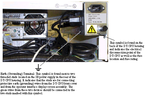
 When replacing a fuse, use only fuse type T3.5A, 250 VAC.
 This symbol is defined as: Consult documentation to find out the nature of the potential HAZARD and any actions to be taken.
Reference explanation of symbols found on equipment
 This warning label and its contained symbols will be found on the front of the caster base on which the SCM and DM may be mounted.
This warning label and its contained symbols warn of the potential of the SCM and DM tipping over and the need to fully extend the front leveling feet prior to using or stocking the equipment.
Reference explanation of symbols found on equipment (cont’d)
MedSelect, SupplySelect, and Centrack are systems that control access to the contents of cabinets through electronic locking mechanisms. MedSelect is primarily used for controlling access to pharmaceuticals; SupplySelect is used to control access to non-pharmaceutical healthcare supplies. Centrack is a separate software application that provides record keeping and supply tracking of controlled substances that are kept in a pharmacy vault.
Each MedSelect or SupplySelect system includes a central computer, any number of dispensing stations throughout the facility; and a server that facilitates communication between the stations and the computer. The central computer for a MedSelect system is called the Administrative Work Station (AWS) and resides in the facility pharmacy, while the central computer for a SupplySelect system is called the Control Center and is under the control of the Supplies department. If a MedSelect system, a SupplySelect system, and a Centrack Terminal (CT) are in a single facility, they may share a server.
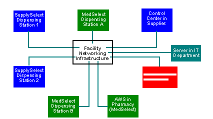
The server and the central computers are set up prior to the installation of stations. The facility sets up its networking infrastructure prior to the installation of the dispensing station equipment so that network ports are available in dispensing station locations by the time station installation starts. In a typical installation of a dispensing station, moving and mounting the cabinets is done by one or more people; when the cabinets for an entire station have been mounted, the display terminal is installed, the station components are connected, and the installation is tested.
This guide provides procedures, guidelines, and checklists for installing dispensing station equipment. Although the steps for installing a dispensing station depend on the mix of components ordered by the customer, the procedure is generally as follows:
Ensure that all packages shipped have arrived at the customer site undamaged and that all required components are in the packages. For more information, see Chapter 2.
In order to minimize disruption of a facility’s operation, initial setup of components is typically performed in a staging area instead of in their final locations. Staging includes performing any necessary pre-assembly steps. See Chapter 3.
Components are delivered either on pallet, which must be moved by ABTG-sanctioned personnel, or on wheels, which can be moved by site personnel.
Once stations are pre-assembled, the components can be moved to their final locations and attached to permanent mounts. Components can be mounted in a variety of ways: on the floor, under a countertop, or on top of a component. For more information, see Chapters 4, 5, and 6.
When all station components are mounted, they can be connected to each other and to power. Prepare the DT and download the latest DT application from the server. For connection procedures and DT application downloading, see Chapters 7 and 8.
Computer systems are powered on, and each mechanical device is operated to ensure that it functions properly as described in Chapter 9.
To maintain the professional appearance and goodwill of ABTG, all work areas must be left as clean as they were found. All packing materials and supplies used during installation must be removed unless the customer assumes this responsibility. For cleanup guidelines, see Chapter 9.
The dispensing station is turned over to the customer and the customer’s signature indicates approval of the installation. For more information, see Chapter 9.
Procedures may vary depending on the facility. If you are uncertain of procedures, contact the project manager.
Dispensing Station Components
A dispensing station is one or more cabinets that dispense pharmaceuticals or medical supplies and a computer system, called a display terminal (DT), that controls access to the cabinets. A dispensing station is either a MedSelect station, a SupplySelect station or a Centrack station. Although MedSelect and SupplySelect dispensing stations may be collocated in a single area, they are separate and require separate display terminals.
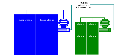
Cabinets
Site requirements define which cabinets are to be installed in each dispensing station. Use the cabinet descriptions below to distinguish one from another.
MedSelect
A MedSelect station may contain any combination of the following components:
Standard Cabinet Module (SCM):
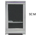 The SCM has a single door with a glass pane. It may be mounted on a base with casters and levelers, a DM, another SCM, a counter, to the floor using a seismic kit or be tethered to the facility for security. The dimensions are 22.8” W x 27.6” D x 34.4” H (w/o base), 39.4” H (with base). Estimated weight is 232 lbs (w/o shelves and counterweight), 425 lbs (with shelves), 605 lbs (loaded). The base weighs approximately 70 lbs.
The DM utilizes drawers and configurations vary, so the DMs in your installation may not have the same number or placement of drawers as those shown here. A DM always has a base with casters and levelers. It may be mounted to the floor using a seismic kit or be tethered to the facility for security. A CDM, UDM, SCM, DT-CPU or DT-UI may be mounted to it. The dimensions are 22.8” W x 27.6” D x 39.2” H (w/o base), 44.2” H (with base). Estimated weight is 245 lbs (w/o drawers), 746 lbs (unloaded), 836 lbs (loaded). The DM base weighs 70 lbs.
The UDM has a cavity and a locking door in the front. It may be mounted on a DM, an SCM or counter (standard or seismic). The dimensions are 22.8” W x 27.6” D x 26.0” H. Estimated weight is 108 lbs (w/o shelves), 197 lbs (with shelves), 250 lbs (loaded).
The CDM is similar to the DM but only has four rows of drawers. It may be mounted on a DM, a UDM, an SCM, another CDM or a counter (standard or seismic). The dimensions are 22.8” W x 27.6” D x 14.3” H. Estimated weight is 32 lbs (w/o drawers), 232.5 lbs (unloaded), 268 lbs (loaded).
MedSelect/SupplySelect
The TM is used for both SupplySelect and MedSelect dispensing stations. It has four doors with glass panes. Installation of the tower may include modifications, such as reversing the door hinges, joining doors so that two or more open together, and moving shelves from one location to another. Tower installation includes the insertion of shelves, bins, and shelf dividers. It has casters and levelers. The dimensions are 27.8” W x 28.9” D x 77.4” H. Estimated weight is 574 lbs (empty), 1,250 lbs (loaded).
Install an ELM when a customer needs access to other devices, such as a refrigerator or cupboard, to be electronically controlled by the MedSelect or SupplySelect system.
All mounting decisions must be made by the time installation begins. Installers will use the Implementation Drawing to determine which method to use. Refer to the chart below to determine which component is used with which system:
Display Terminal and Electronics
The DT is the computer system that controls access to the modules. It also powers the modules in MedSelect and SupplySelect stations. Each DT has a CPU (DT-CPU) and a user interface (DT-UI).
If the SupplySelect station only uses a tower module, the power from the UPS is bypassed. When other modules are added, an inventory bus repeater (IBR) is not required because the DT has a UPS. An IBR may be required depending on cable length and module count. Each DT has a CPU (DT-CPU) and a User Interface (DT-UI).
Display Terminal CPU (DT-CPU):
Computer (DT-CPU PC):
This is the computer that controls cabinet access.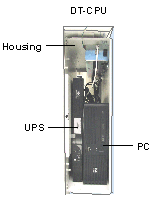
Uninterruptible Power Supply (DT-CPU UPS): This ensures that the electronic components continue operating during a power failure, power fluctuations or brown-outs.
Display Terminal Housing (DT-CPU Housing): Installing the DT includes mounting the housing for the PC and UPS. It can be mounted horizontally on a DM, a UDM, an SCM, a CDM, a TM or a on/under a counter (standard or seismic) or vertically on a DM, an SCM, a TM or a wall (face not up or down). The dimensions are 22.8” H x 25.6” D x 6.7” W. Estimated weight is 17.5 lbs (empty), 69 lbs (PC and UPS).
Display Terminal User Interface (DT-UI):
This is the monitor and keyboard that the clinician uses to request access to the cabinets. The DT may be mounted on a UDM, an SCM, a TM, a wall or stand on any component or counter. The dimensions are 16” W x 12.0” D x 18.0 H”. Estimated weight is 26 lbs. It may include any of the following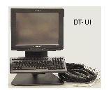 :
:
card reader (magnetic swipe, barcode swipe or proximity)
Electronic Lock Controller (ELC):
Controls the locks if the system has an External Lock Module (ELM) or a Standard Cabinet Module (SCM).
MedSelect Inventory Bus Repeater (IBR):
As modules and distance are added, the signals weaken. An IBR is inserted between modules to boost the DT signal, if required.
Centrack Inventory Bus Hub (IBH):
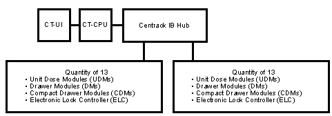
When modules are used with Centrack software, an IB hub is required to distribute the IB signal and power from the CT. For information about Centrack, see Chapter 10.
Required Installation Tools and Equipment
The tools, supplies, and test equipment required when installing this equipment are specified in the installation procedure for each component. The following lists are comprehensive, including all tools specified in the individual procedures.
For Mounting Modules and Towers
An assembled tool kit is available for installation personnel. If a procedure specifies the use of a tool in the tool kit, the supplied tool must be used. Installation requires the common tools listed in the tables below:
7/16” |
||
9/16” |
||
15/16” |
||
1-1/8”, deep well |
||
17 mm (11/16” allowed) |
||
< 20 in-lb |
||
11 ft-lb |
(Recommended in non-seismic areas for Tower and older-style module floor mount) |
|
20 ft-lb |
||
40–60 ft-lb |
||
150 ft-lb |
||
For Installing Display Terminals
Perform these procedures to ensure that all equipment shipped has arrived at the customer site undamaged. As a result of this process, you will also have grouped components by the locations in which they will eventually be installed. As with all procedures, yours may vary depending on the circumstances at the facility. If at any point you are uncertain of how to proceed, contact the project manager.
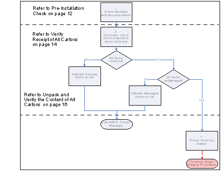
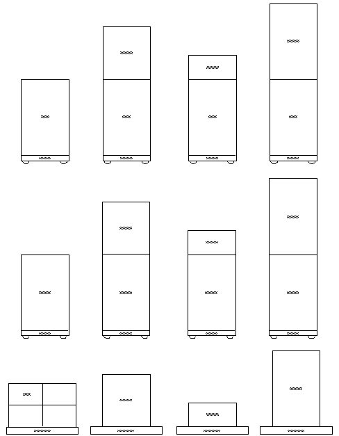
Refer to See Shipping Configurations for a description of how modules are shipped.
Pre-Installation Check
Review the following information before beginning an installation.
Notify the project manager and pharmacy administrator before beginning installation.
Find out from the project manager whether unpacking is to be done in the receiving area or in a separate staging area.
Most facilities provide a staging area in which you can perform modifications that need to be made before mounting cabinets in their final locations. Depending on facility constraints, the staging area may accommodate only one station at a time, or it may be large enough for the entire installation shipment. If there is no separate staging area, the receiving area usually becomes the staging area.
Review all of the installation documentation supplied by the project manager for the placement of equipment.
The project manager is the holder of all installation documentation, which includes site layouts, worksheets, and checklists. At the end of the installation, turn over all installation documentation and the cabinet keys to the person designated by the project manager (usually a hospital administrator).
You must be in possession of all required installation documents before the installation can proceed. If you do not have them, contact the project manager before going ahead.
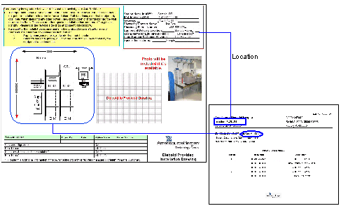
A Shipping Label is attached to the outside of each carton or shrink-wrapped bundle. Use the “Location” to group items by dispensing station.
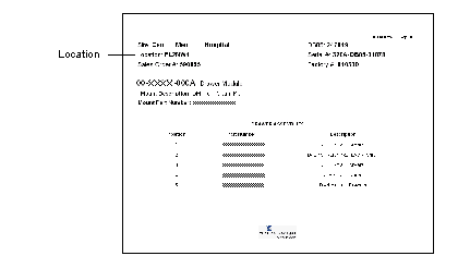
The “Location” field indicates the dispensing station.
Installation worksheets are shipped with the equipment and are either inside or attached to the outside of the equipment. The shipment contains one worksheet for each major component, such as a drawer module. The worksheet contains configuration information for the component, such as a list of drawer assemblies present in a drawer module. Additionally, the worksheet lists the controller address for each addressable location within the component.
The worksheet may include specific configuration instructions, which must be followed. Use this document to identify and record configuration changes. Any changes made to the component at the customer site must be recorded on the worksheet prior to turning over the installation documentation.
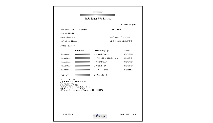
(Drawer Module worksheet shown).
Implementation Drawings (may not be present) include basic system layout and equipment specifications for a dispensing station.Use these drawings to verify receipt of all components in the station and to determine the relative placement of each component in the dispensing station. Implementation Drawings are provided by the project manager
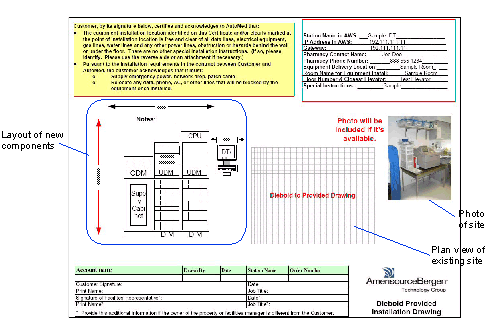
Verify Receipt of All Cartons
This method of receipt verification is suggested to help you sort through the large quantity of received items in large installations. This method can be performed only if your installation documents include Station Drawings. If you do not have them, skip the remainder of this chapter and proceed to Chapter 3.
The object of this procedure is to verify that:
All equipment received is undamaged.
All required equipment has been received.
The equipment may arrive (with packaging) on either a pallet or with casters (TM, DM and SCM only), depending on how it was ordered.
If you are installing more than one dispensing station, contact the project manager to determine which station is installed first. Using the Station Drawing for the first station, find each pallet that belongs to it. Find each component, identify it by the location and component name on the box label and check it off on the Station Drawing. The station is identified as “Location” on the shipping label on the outside of each package as shown:
For each pallet belonging to the station,
Check the tilt indicator on the package. If a tilt is indicated, contact the project manager and hospital administrator or other customer contact.
For a carton: On the Station Drawing, place a check mark next to the part name for each component identified on the carton.
For a shrink-wrapped package: Display terminals (DTs) for more than one station may be packaged together. Separate them and identify the one that goes with your Station Drawing:
Remove and retain all documents attached to the outside of the package.
Remove the packing straps that secure the package to the pallet.
While still using the same Station Drawing, find and remove each box that belongs to the station.
Place a check mark next to the part number for each box belonging to that station’s DT on the Station Drawing.
Move the package or DT boxes to the staging area for the station. If the stations are to be staged in the receiving area, move the package off to the side with other packages for the same station and away from unverified cartons.
Cabinets, mounts, shelf options and cabinet options for a particular dispensing station are grouped by the sales order number and must be kept together.
Continue checking and moving packages while working off of one Station Drawing until no more unverified packages exist for that station. If the Station Drawing has any items without a check mark, the item is missing. Double check the receiving area and if the package is missing, call the project manager.
If the staging area is large enough to accommodate all the stations, continue checking and moving cartons until all components are grouped by station.
Unpack and Verify the Content of All Cartons
Perform this procedure to verify the cartons contain the required components.
If the cartons are still in the receiving area, move all cartons for the first station to the staging area.
Using the Station Drawing for the first station, remove the packaging for the first listed component.
For a module:
There are two ways a module(s) can be shipped to a site: on a pallet or on the module’s casters. Refer to the Flex Shipping Configurations graphic at the end of this chapter for an illustration of the combinations.
For modules shipped on either a pallet or casters: Remove the shipping label from the carton and retain it along with the other documentation to be turned over when installation is complete.
For a module(s) shipped on a pallet: Cut the packing straps and loosen the staples that attach the cardboard box to the pallet. Lift and discard the cardboard box covering the module(s).
For a module(s) shipped on casters: Cut the packing straps and remove all the shrink wrap from the module(s).
For either modules shipped on either pallet or casters: Remove the contents of the cardboard spacer on top of the cabinet. It should contain the following items for each module in the carton:
A mounting kit is supplied and needs be mounted. Consider keeping the TM permanent mount hanging on the underside of the TM for ease of transport when installing at the dispense station.
Two cabinet keys and key tags per cabinet
(Optional) Special Instructions
If the module has special instructions, be sure to follow them. Special instructions supersede instructions in this guide.
If any of the above items are missing, call the project manager.
Verify that the keys operate the door locks.
Put all keys and key tags for the dispensing station in a box or bag. The keys are used to open equipment during installation or if there is a power failure or other emergency. If the tags are not identified, it is difficult to match a key to its cabinet. Missing/lost keys can be replaced through Diebold Banklock.
The key tracking process is defined in the planning stage by the project manager. Refer to the installation documentation provided by the project manager.
Repeat steps See For modules shipped on either a pallet or casters: Remove the shipping label from the carton and retain it along with the other documentation to be turned over when installation is complete. through f for each module carton belonging to the station.
For a Display Terminal:
One or two display terminals can be shipped on a pallet. Boxes may be removed from the pallet for ease of transport.
Boxes only need to be opened if damage is suspected. Do not remove components from the DT.
Do not discard the box until each component is secured to the station.
Some items are optional to the customer and may not be a part of the installation.
|
Computer (box is labeled as containing a computer - ensure security) |
|
|
Monitor and Keyboard with cable bundle |
|
If any required component is missing, contact the project manager.
The label shown is for the DT-CPU PC.
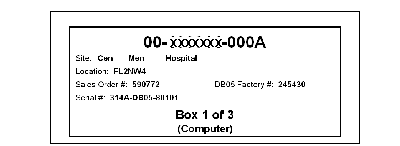
Staging the components ensures that they work as intended; staging also minimizes disruption prior to placing components in their final locations. If equipment is being installed in an operational healthcare facility, minimizing disruption of a live dispensing station is essential to a successful installation. Once you know that all items for a single station are present and undamaged, you can start performing any modifications and unit testing of the components in preparation for the move to their final locations.
The station may be assembled at the staging area since many module configurations are on casters. For stations that are assembled in the staging area, refer to chapters 4, 5 and 6 for instructions to perform assembly. Some modifications will be in the MedSelect Flex SupplySelect Centrack Restocker Guide and some can only be performed by ABTG-sanctioned personnel.
Typically, components are configured to order before they are shipped, but sometimes changes are needed at the installation site. Additionally, shelf options (such as bins and dividers), and uninstalled cabinet options (such as door joining kits) are shipped with, but not in, each cabinet, and can be installed in the staging area. The original specifications in the installation documentation cannot be changed without the documented consent of the customer. If any deviation is required, the installer must obtain prior approval from the project manager before continuing with work.
The following tasks are part of staging; skip those that do not apply to your installation:
Changes that you may need to make to modules start on See Module Staging.
Final unpacking and changes that need to be made to tower modules in either a MedSelect, a SupplySelect or a Centrack system start on See Tower Module Staging.
: In some installations, cabinets will be stocked with supplies and medications before they are moved to the dispensing station. Stocking is typically performed by the customer, and, in the case of prescription medications, must be done by the customer. For clarification, see See Required Precautions When Working in Area of Controlled Substances at the front of the guide . The customer can find stocking instructions in the MedSelect Flex SupplySelect Centrack Restocker Guide.
See Moving Cabinets to Permanent Locations:
Read the considerations for moving cabinets in this chapter on See Moving Cabinets to Permanent Locations.
All components must be unpacked and verified, see See Unpack and Verify the Content of All Cartons before staging.
Module Staging
This section provides instructions for staging the following modules:
See Standard Cabinet Module (SCM)
Standard Cabinet Module (SCM)
The following changes may be applied to SCMs:
To move a sliding or fixed shelf, follow the instructions in See Moving a Sliding Shelf and See Moving a Fixed Shelf.
To remove, insert, or replace shelf dividers, follow the instructions in See Shelf Dividers.
To change the door swing, follow the instructions in See SCM Door Reversal.
Shelves
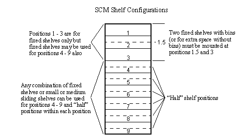
Both sliding and fixed shelves can be moved to different locations. The SCM is shipped with the shelves and slides installed as ordered, but if you need to change their placement, refer to the following graphic for the various configurations.
When changing to the 1.5 or “half” position for shelves with bins or for extra space without bins, the bin support clips must be moved accordingly.
Moving a Sliding Shelf
Pull the shelf out of the cabinet until it is fully extended.
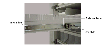
Press down on the right slide release lever and up on the left slide release lever and continue to pull the shelf out until it is free of the cabinet.
Move the outer slide along with the shelf to the new location. The SCM may use more than one kind of slide. Not all inner slides are compatible with all outer slides.
To remove the outer slide, first tilt the bottom of the slide away from the cabinet, then lift the slide up and away from the cabinet.
Insert the outer slides in the new location.
Fit the inner slide back into the outer slide, and slide the shelf back into the cabinet in the new location.
Shelf Dividers
Divide a sliding shelf into compartments using interlocking dividers.
A vertical divider runs from the front to the back of the shelf.
A horizontal divider runs from the left to the right side of the shelf.
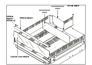
Also shown is an optional clear window at the front of the shelf. A metal window support, secured at each end by a screw, holds the window in place.
A fixed shelf uses vertical dividers only.

SCM Door Reversal
The door is symmetrical and can be attached to either side of the cabinet, allowing for either left- or right-side opening. If you need to reverse the door, follow the procedure below.
#2 Phillips head screwdriver
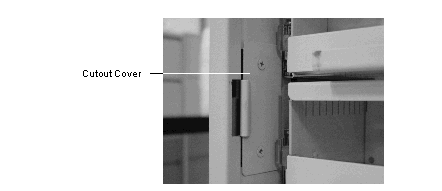
Remove the two hinge cutout cover plates from the opposite hinge side of the cabinet. Each cover plate has two screws. Save these parts.
Drawer Module (DM, CDM)
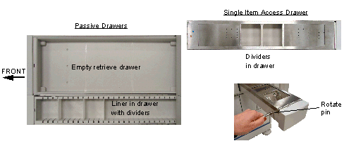
Most drawers can be divided into compartments. To do this, a plastic liner is placed into the drawer. The liner is slotted to accept dividers that can be configured in a variety of ways. The dividers slide in and out of the liner without need for any special tools, and can be easily relocated to allow for a variety of different supply shapes and sizes. Large non-retrieve passive (non-single-item access) drawers use dividers placed along either the length or the width of the drawer.
Single item access (SIA) drawers can be separated into either six compartments (all small) using three dividers, or three compartments (all large) using no dividers. The belt can be manually moved using the slotted key to rotate the pin.
Unit Dose Module (UDM)
The dispensing shelves in a UDM are configured to order at the factory, and each shelf contains either dispensing helixes or dispensing bins. Each UDM has five shelves, which are numbered sequentially, 1–5 starting with the top shelf. For shelf order within the UDM cabinet, refer to the Installation Worksheet.
All items in a shelf must be removed by site personnel before a shelf is removed.
To remove a helix shelf, follow these steps:
Open the UDM door and swing it down to its full open position.
Support the weight of the shelf, press down on the shelf release tabs and let the shelf slide out until it is fully extended.
Press up on the left slide release lever and down on the right slide release lever and continue to pull the shelf out until it is free of the cabinet.
Support the shelf upside down and release the reusable cable tie.
Disconnect the cable from the shelf, and remove the shelf.
Do not disconnect the cables from the rear of the cabinet.
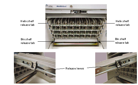
UDM Helix Shelf Removal
Connect the cable to the shelf and secure it with the cable tie.
Push the shelf and bins into the UDM until the release tabs catch.
To remove a bin shelf, perform the following:
Open the UDM door and swing it down to its full open position.
Press down on the shelf release tabs (refer to the picture above) and slide the shelf out until it is fully extended.
Pull back on the front cover and tilt it forward.
Move the bins to the side and disconnect the bin connector from the board.
Support the shelf, push the tie strap tang to release the cable tie.
Disconnect the shelf cable from the board.
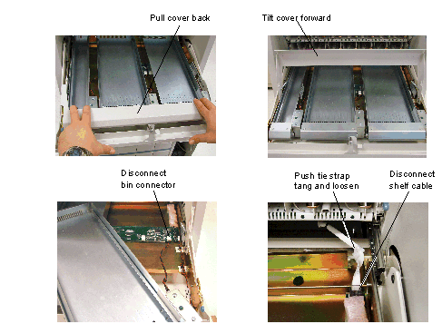
UDM Bin Shelf Removal
If you need to reconfigure a shelf, refer to the MedSelect Flex SupplySelect Centrack Restocker Guide for detailed instructions and bin connections.
Reconnect the shelf cable connector and tighten the tie strap and ensure the tie strap is in the same position it was originally in to prevent interference.
Connect the bin connector to the board and place the bin in position.
Place the tilt cover in position.
Push the shelf and bins into the UDM until the release tabs catch.
Tower Module Staging
 Only qualified MedSelect authorized service personnel may move and install a tower module cabinet. Do not remove the liability label on the top door window of a cabinet until instructed to do so. Cabinets that are being moved can be tilted over and cause serious injury and damage.
The cabinet must be stabilized in a mount before you can begin any work on a tower module. In the staging area, use the temporary floor mount to provide side-to-side stability. Once the tower module is mounted, you can continue with the following staging procedures, if required for your installation:
Shelf, bin, and divider installation
 A temporary or permanent mount must always be used except during movement of the cabinet by qualified ABTG contracted service personnel. A cabinet may not be stable without a mount and could tip over, causing serious injuries.
Customer Configuration of Shelves, Shelf Bin & Divider Installation, Stocking & Labeling
The customer can now decide how the shelves should be stocked. You may rearrange the shelves and bins and install the dividers at this point, as the customer decides the optimal setup of each cabinet. If you need to assist the customer, refer to See Shelves, Shelf Dividers, and Bins.
The customer can also move the shelves, bins, and dividers without assistance - refer to the instructions in the MedSelect Flex SupplySelect Centrack Restocker Guide (a customer document).
The customer may also label the shelves and bins at this time, using the color Position Indicator Labels (included with the cabinet) and Position Labels (printed at the customer Control Center PC). Labeling instructions are found in the MedSelect Flex SupplySelect Centrack Restocker Guide .
Temporary Floor Mount Installation
A temporary floor mount (P/N 49-017178-000A), illustrated in See Temporary Floor Mount, is available for any installation that includes a tower module. If the mount is not already in the staging area, find it in the receiving area and move it to staging.
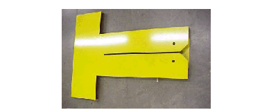

Make sure that the doors are latched shut before installing the temporary floor mount. This prevents the doors from opening while the cabinet is being moved into position for configuration.
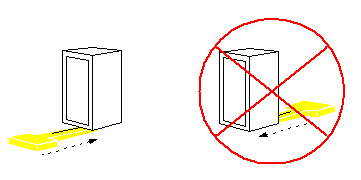
 When in the temporary floor mount, the cabinet can become unstable side to side or from the front.
The temporary floor mount is not secured to a fixed surface such as a floor or wall. This mount is intended to provide a temporary stable surface between the bottom of the tower module and the floor so that tilting will not occur during configuration. Follow these steps to install the temporary floor mount:
Position the tower module with at least three feet of clearance on each side.

Remove the bolt (3/8”-16 x 1”) stored on the side of the temporary floor mount.
Push the mount beneath the tower module from the front until it stops.
Drop the 3/8”-16 x 1” bolt through one of the holes in the temporary mount and into one of the two holes in the channel inside the cabinet at the rear of the tower module (you must reach inside the channel to do this). The bolt is not screwed down as a fastener, but acts as a pin within a confined area.
Push (do not tip) the tower module backward and confirm that it cannot be pushed off the mount.
If the tower module can be separated from the mount, the bolt is not properly engaged. Repeat steps and See Push the mount beneath the tower module from the front until it stops., See Drop the 3/8”-16 x 1” bolt through one of the holes in the temporary mount and into one of the two holes in the channel inside the cabinet at the rear of the tower module (you must reach inside the channel to do this). The bolt is not screwed down as a fastener, but acts as a pin within a confined area., and See Push (do not tip) the tower module backward and confirm that it cannot be pushed off the mount. until pushing the tower backward does not separate it from the mount.
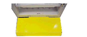
Door Hinge Reversal
If a door or hinge is damaged and requires replacement, refer to See Removing the Doors and Hinges and perform steps 3 - 5 to remove and reverse the order to replace.
If the tower module requires both door hinge reversal and door joining, perform door hinge reversal first .
#2 Phillips head screwdriver – straight shaft
#2 Phillips head screwdriver – 90°
Each tower module is typically shipped with the door orientation defined in the installation planning documentation. However, a door hinge side reversal kit is shipped with each tower. The tower is designed for making this change without additional assemblies or parts. All doors on a single tower must have the same hinge-side orientation since adjacent doors are hinged together.
Reversing the hinges includes the following steps, which are detailed in this section:
Reroute the wiring (See Rerouting the Wiring)
Remove all doors (See Removing the Doors and Hinges)
Reverse the hinge and lock rails (See Reversing the Rails)
Replace all doors (See Replacing the Doors and Hinges)
Rerouting the Wiring
The wiring that controls the locks runs from the top of the tower module down to each lock behind the lock rail. You must move the wiring in the lock rail to the opposite side of the cabinet when you move the locks to the opposite side. Reroute the wiring as follows:
Install the temporary floor mount (see See Temporary Floor Mount Installation).
Remove the small and large covers from the top of the tower module, refer to See Changing the DIP Switch Settings.
Disconnect the four lock harness connectors from the lock CCA:
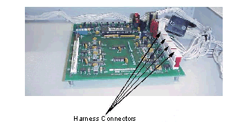
Cut the two cable ties holding the lock harness to the front vertical surface of the top compartment and the one beside the CCA:
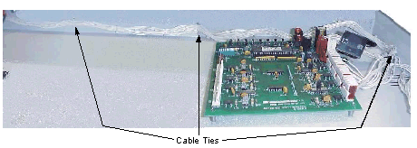
Remove the 10 hole plugs from the hinge holes from the lock rail (see the following figure).
The lock rail has five front screws and eight side screws: Remove the front screws and loosen the side screws (there are open slots in the rail).
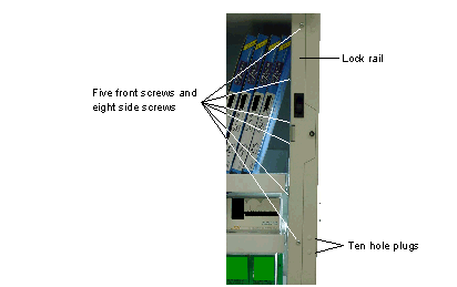
Guide the lock harness down through the grommet from the top compartment.
Lay the lock rail on a flat working surface and cut the single end cable tie that secures the cable to the rail via a cable mount.
Flip the harness so that the connectors are at the other end of the rail.
Pull the harness tight and secure it to the cable mount with a cable tie.
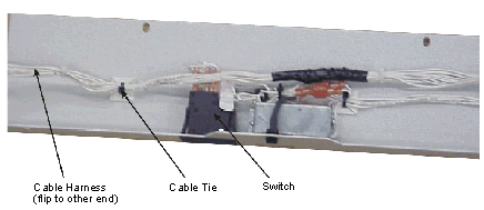
Removing the Doors and Hinges
Temporarily label the doors 1–4 as shown below; this is the order required so the lock rail and doors are paired as before.
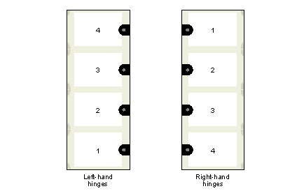
Remove the 10 hole plugs from the unused hinge holes from the lock rail (See Lock Rail.).
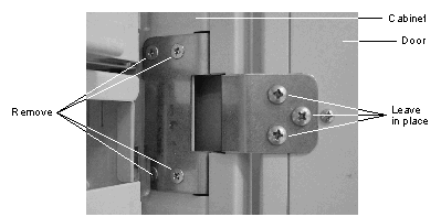
Remove the two screws on both hinges that secure the door (See Door to Hinge and Hinge to Cabinet).
Continue until all doors are removed.
Remove the three screws securing the hinge(s) to the cabinet.
Continue until all hinges are removed.
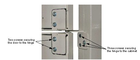
Reversing the Rails
Remove the eight screws securing the hinge rail to the cabinet.
Move the hinge rail to the opposite side of the cabinet; do not securely tighten the five front screws at this time.
Attach the lock rail to previous hinge side as follows:
Flip the lock rail so that the cable harness connector end is at the top of the rail.
Feed the harness end (connector end) through the left side grommet and into the top compartment.
Verify that all rail wires are inside the rail so that they are not pinched when fastening the rail to the cabinet.
Verify that all LEDs are snapped into their retainer and that all push-on connectors are connected.
Reinstall the lock rail. Do not securely fasten the five front screws at this time; they will be tightened during the lock adjustment step, refer to steps 4 - 12 in See Replacing the Doors and Hinges.
Connect lock harness connectors to the lock CCA (See Harness Connectors).
Connectors are labeled LEFT or RIGHT lock rail installation. The number following the label designation LEFT or RIGHT refers to the mating CCA connector. For example, LEFT 4/RIGHT 1 denotes that the connector connects to J4 on the CCA for a left-sided lock rail and J1 for a right-sided lock rail.
Secure the lock harness to the vertical front face of the top compartment.
Use two tie straps (tie mounts factory installed) for a right lock rail, and one tie wrap for a left lock rail.
Always route the cable beneath the light power switch wires. It is necessary to fold back the cable as shown when using one tie strap.
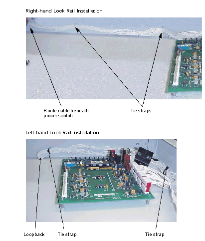
Replacing the Doors and Hinges
Refer to See Labeling the Doors Before Removal for left- and right-hand hinge door numbering.
Refer to See Door to Hinge and Hinge to Cabinet for door-to-hinge attachment and hinge-to-cabinet attachment.
The top and bottom hinge locations on the cabinet must be switched. Remove the top hinge on one side and use it as the bottom hinge on the other side, and vice-versa. The three middle hinges can be located anywhere on either side.
Install the hinges in their respective positions on the cabinet.
Install each door to its respective hinges.
Remove temporary labels from doors.
Align the door locks horizontally:
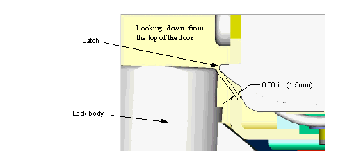
Close the top door and observe the clearance between the body of the lock (not the bolt of the lock) and the latch on the lock rail.
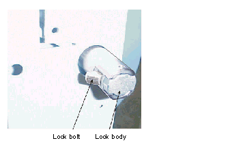
The body of the lock must just clear the latch in the lock rail. The gap between them must not be more than 0.06 in. (1.5mm).
Observe the horizontal alignment between the keeper on the door and the switch/catch on the lock rail. The keeper must not touch the body of the switch/catch.
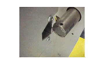
If either the lock body or the keeper are out of alignment with the lock rail, adjust the horizontal position of the lock rail as follows:
Loosen the five front lock rail screws.
Move the lock rail horizontally until the lock body just clears the latch and the gap is not greater than 0.06 in. (1.5mm).
Ensure that the keeper on the door is aligned vertically with the switch/catch on the lock rail. The keeper should not touch the pawl or body of the switch/catch on the lock rail when closing the door.
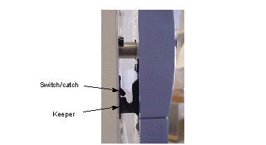
Keeper and Catch/Switch Alignment
If the keeper touches the pawl or body of the switch/catch, adjust it as follows:
Loosen the two screws on the keeper.
Repeat steps See Align the door locks horizontally:–See Align the locks vertically: for the remaining doors.
With the doors open, turn each key lock counter-clockwise to extend the lock bolt of each lock.
Close all doors and verify that they are locked and held firmly closed.
Electronically open each door by pressing the corresponding test button (SW1, SW2, etc.) simultaneously with SW11 on the lock controller CCA (See Circuit Card Assembly (CCA) for a pictorial reference).
Door Joining
If the tower module requires both door hinge reversal and door joining, perform door hinge reversal first (instructions begin on See Door Hinge Reversal) .
Adjacent doors can be joined so that they function as a single unit. Joining doors includes the following steps, which are detailed in this section:
Installing the door joining kit (See Installing the Door Joining Kit)
Setting the locks mechanically (See Setting the Locks)
Verifying the door alignment (See Verifying Door Alignment and Closure)
Changing DIP switch settings accordingly (See Changing the DIP Switch Settings)
Update the installation documentation (See Updating the Installation Documentation)
Tables in these instructions refer to the doors by the following numbers:
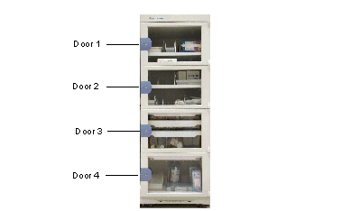
Installing the Door Joining Kit
Install the temporary floor mount (see See Temporary Floor Mount Installation).
Unlock and open the two doors to be joined.
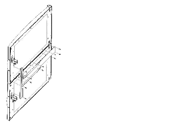
Remove the three #10 screws on the bottom of the top door and the three #10 screws on the top of the bottom door.
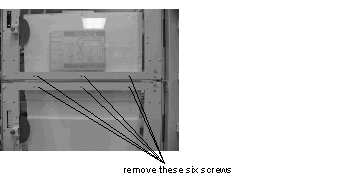
Setting the Locks
Lock the required door and unlock those joined to it according to the table below.
Clean the lock plate, peel a lock cap from the sheet, and place the cap over the lock for each unlocked door.

Verifying Door Alignment and Closure
Modify the door positions if the doors do not line up vertically.
Use See Door to Hinge and Hinge to Cabinet as a pictorial reference for door-to-hinge attachment.
Close cabinet doors and inspect the door alignment. If a door is misaligned, loosen the two door-to-hinge screws and move the door up or down. Tighten the screws.
Once the doors are aligned, confirm that they open and close smoothly. If any door does not open or close smoothly, adjust the door again.
Once the doors are aligned and open and close smoothly, lock the door lock(s).
Changing the DIP Switch Settings
When doors are joined, one is locked while the doors joined to it remain unlocked. This change in mechanical locking configuration must be reflected in the electronic locking mechanism. To reflect this, set the DIP switches in the top of the cabinet as follows:
Remove the two #10 screws that secure the front cover plate, and remove the plate to reveal the circuit card assembly (CCA).

Using a pen point, position the DIP switches for the appropriate door locking mechanisms according to the table below.
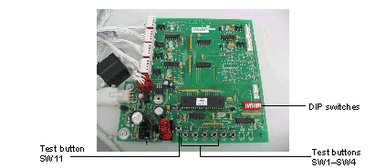
Security Divider Installation
A security divider prevents access to a lower compartment when an upper door is opened. Do not place security dividers between doors that will be joined.
#2 Phillips head screwdriver
The security divider is installed between shelves at a door division and secured by four screws. Holes are pre-drilled into the inside right and left side panels of the cabinet. Install the security divider as follows:
Remove any shelves near the door division to allow enough room to work.
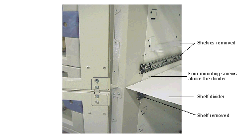
Position the divider as shown in See Security Divider Installation. Be sure that screw holes in the bracket are above the divider and not below it.
Secure the brackets to the inside cabinet walls using the screws provided in the security divider kit.
Shelves, Shelf Dividers, and Bins
The customer may also label the shelves and bins at this time, using the color Position Indicator Labels (included with the cabinet) and Position Labels (printed at the customer Control Center PC). Refer to the MedSelect Flex SupplySelect Centrack Restocker Guide user document for labeling instructions.
A tower module can have two kinds of shelves: fixed and sliding.
rest on removable rails that hang on tabs. A fixed shelf can be divided with fixed shelf dividers, and further divided with bin dividers.
(short or tall) are attached to removable sliding rails and contain a clear, suspended bin. A sliding shelf can be divided with short or tall sliding shelf dividers.
Only fixed shelves may be used in the top six positions (all for door #1, top half of door #2).
Moving a Fixed Shelf
Push the shelf up from the bottom and slide it out until it comes out of its rails.
Lift the shelf out of the cabinet.
Lift the shelf rails out of their slots and move them to the new location.
Moving a Sliding Shelf
Pull the shelf out of the cabinet until it is fully extended.
Press up on the left release tab and down on the right to release the shelf from its the outer slide.
Pull the shelf out until it is free of the cabinet.
Lift the outer slides out of their slots and move them to the new location.
Fit the inner slide back into the outer slide, and slide the shelf back into the cabinet in the new location.
Moving Shelf Dividers and Bins
Line the divider tabs up with the two slots on the bottom of the shelf. Make sure the rear tab of the divider is inserted in the slot at the rear of the shelf.
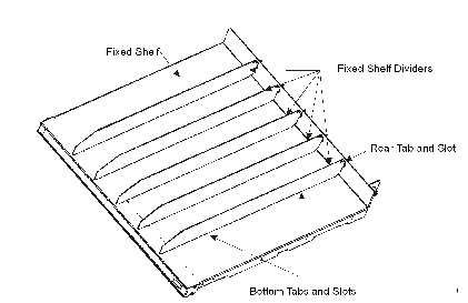
Push down on the divider so the tabs go through the bottom slots.
Grasp the divider firmly and push it toward the back to lock it in place.
To remove a fixed shelf divider:
Grasp the front of the divider and pull it toward you to unlock it.
Lift up on the divider to release it from the bottom slots first, then the rear slot.
To add a fixed shelf bin divider, slide the divider into any available bin slot:
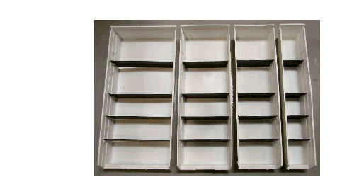
The graphic above shows more than two dividers to provide an illustration of the various divider positions. Use one or two bin dividers for configuration purposes.
To add a sliding shelf divider:
Sliding shelves have vertical and horizontal dividers. A vertical divider has two slots that accommodate horizontal dividers; a horizontal divider has five slots.
Slide a vertical divider, with its slot openings facing up, into any of the five available shelf slots.
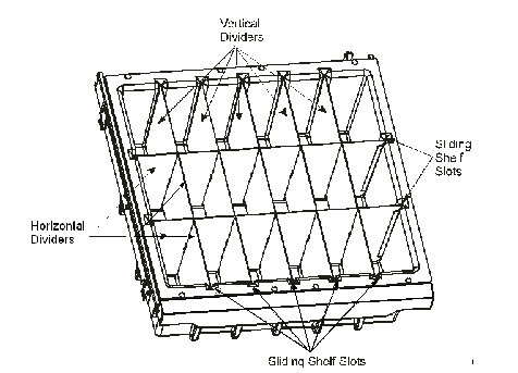
Sliding Shelf with Sliding Shelf Dividers
When all of the vertical dividers have been added, insert a horizontal divider, with its slot openings facing down, into either of the available shelf slots.
The horizontal divider interlocks with the vertical dividers.
To remove sliding shelf dividers:
Remove the horizontal divider(s) from the two available bin slots.
Remove the vertical dividers from any of the five available bin slots.
Repositioning Catheter Rails
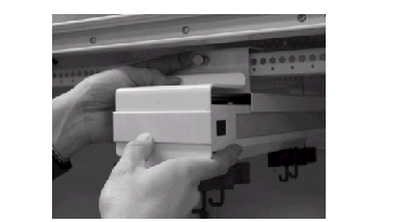
To reposition a catheter rail:
Unlock and open the tower module door.
With your right hand, grasp the rail front; with your left hand, pull the front pin on the rail, releasing the pin from the hole and releasing the front of the catheter rail.
Moving Cabinets to Permanent Locations
 Only qualified ABTG authorized service personnel should move cabinets. If the customer chooses to move the cabinets, the customer must assume all responsibility and liability for the safety of personnel and damage to cabinets.
The following procedures must be performed before moving cabinets from their staging areas to permanent stations:
If any back panels were removed from the cabinet, re-install the panels.
Disconnect all power cables and IB cables from the wall. Keep appropriate power and IB cables with each cabinet.
Unplug interconnecting cables between component stack.
Move levelers up (except tower modules).
Remove the temporary mount and keep it for the next set of cabinets.
Never move a cabinet to its final installation location with the temporary floor mount installed. Remove the mount and return its pin (bolt) to bolt hole storage location on the side of the mount.
The equipment may arrive (with packaging) on either a pallet or casters (SCM, DM and TM only), depending on how it was ordered. If possible, the equipment may be wheeled to its permanent location and set in place by lowering the leveling feet.
When moving equipment on casters: Be aware of gaps, i.e., between floors and elevators, inclines that require more than one person to move equipment, and thresholds that require raising /lifting the equipment. Make the necessary adjustments to safely move the equipment.
Install in Final Location: Modules
The instructions supplied with kits supersede any installation information provided in this manual.
Always use the template supplied with the mounting kit. The template contains detailed instructions for all mounting configurations so take the time to read the instructions
before drilling holes
.
Instructions on the Installation Worksheet supersede any information provided in this manual. Fill out the installation worksheet provided with each dispensing module before installing any equipment. This records all important configuration and key assignment information. Follow any other instructions listed on this worksheet.
Before securing a cabinet in place, make IB cable connections to its rear connectors. Refer to See IB Cable Installation.
MedSelect modules can be mounted in many ways and each method has different instructions. The following table identifies the various ways of mounting each module and points to the page number on which instructions for that mounting method start:
When mounting an SCM with its hinged side next to a wall, allow enough clearance to open door far enough to remove the shelves. As a reference, leave a minimum of two inches clearance between the SCM and the wall if the wall extends 11 inches past the front of the SCM. Leave a minimum of four inches clearance if the wall extends 21 inches past the front of the SCM. Also, see DM/CDM clearance on lock side. Refer to the product cut sheets for an illustration of clearances.
Floor Mounting for Seismic Locations
This topic provides instructions for assembling and installing the mounting kit for SCM or DM modules that is compliant with the Office of Statewide Health Planning and Development (OSHPD) regulations for the State of California, covering the California Building Code (CBC) and the International Conference of Building Officials (ICBO).
The mounting plate ships with the SCM or DM. It passes all California seismic requirements defined by OSHPD. The plate provides equivalent UL safety ratings, and tip avoidance, along with ease of installation.
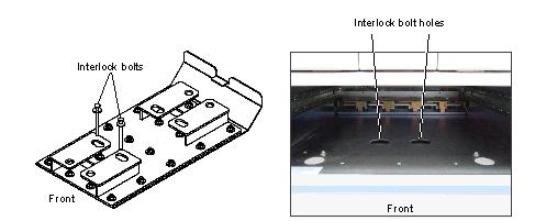
This design ensures that the SCM or DM is securely mounted by floor anchors into approved concrete substrata in the floor. The structural integrity of the substrata must be confirmed by the customer before installation can take place. The mounting design does not require access under the floor for additional hardware and allows mounting in all situations, including ground level or non-accessible lower floors. To secure the SCM or DM to the OSHPD mounting plate, you must first remove the bottom fixed or sliding shelf of the SCM or the necessary bottom drawer(s) of the DM (do not remove the entire drawer assembly) to locate the module over the mounting plate and insert the interlock bolts through the module and into the plate.
Parts and Kits
The tables below provide the part numbers, mounting kit descriptions, and the special tools required to mount the module according to OSHPD regulations for the State of California.
|
Standard Cabinet Module and Drawer Module OSHPD Permanent Mounting Kit Contents |
|
|---|---|
|
3/8” x 3” Strongbolt 2 Expansion Anchors with Washers and Nuts |
|
The base assembly (P/N 10-501221-000A) is provided with the kit and includes a base adaptor that engages the base with the floor mounting kit for seismic installations.
Procedure
|
Drill (heavy duty, hammer type recommended) 9/16” deep well socket and wrench |
This procedure consists of the following steps, each of which is covered below:
Coordinate with the OSHPD compliance officer
Install the Standard Cabinet Module/Drawer Module OSHPD floor mount kit
Install the mount and obtain compliance approval
Engage the SCM/DM to the mount
Coordinate with the OSHPD Compliance Officer
Contact the OSHPD compliance officer and obtain permission to start the installation procedure.
You will also need the compliance officer’s approval during this procedure.
If pre-approved anchorage details and calculations are not yet available, a site-specific approval is required. use the current Medselect Flex calculations (OPA2617-10) to obtain site-specific approval.
Install the SCM/DM Module OSHPD Floor Mount Kit
The permanent mounting plate and mount plate weldment are installed using the supplied anchors, washers, and nuts.
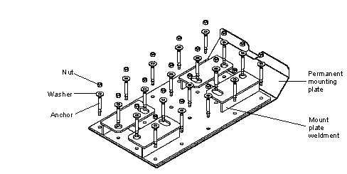
Floor Mount for Seismic Locations.
This procedure covers a single Flex SCM or DM module or module stack and floor mount kit. If you install additional modules and kits, follow these procedures for each installation. Ensure that the mounts are located properly so the cabinets will be adjacent to each other and properly aligned. Install the kit as follows:
Identify any electrical wall outlets or mounted surge protectors that must be taken into account when positioning the modules.
Remove the bottom fixed or sliding shelf of the SCM or the necessary bottom drawer(s) of the DM (do not remove the entire drawer assembly).
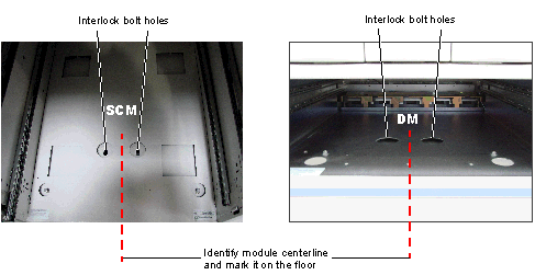
Identify the centerline of the module/module stack and mark the floor or wall in accordance with the module/module stack centerline.
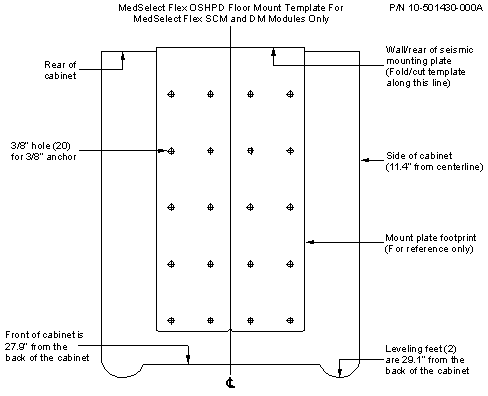
Refer to the notations on the installation template (refer to Figure See OSHPD Floor Mount Installation Template) and cut or fold the installation template according to the desired placement of the cabinet from the wall.
Slide the permanent mounting plate on the floor according to the centerline mark until it touches the wall or otherwise meets your requirement for placement, noting any unusual obstructions that may also need to be taken into account.
Slide the installation template under the permanent mounting plate and match the hole pattern with the holes.
For multiple module installations, allow minimal space between modules/ module stacks. A module is 22.8 inches wide. Consider using a spacing of 23 inches for each module/stack to locate the centerline and place the mount for each module.
Carefully mark the drill locations on the floor using the 20 hole cross marks on the template for the drill locations
Install the Mount and Obtain Compliance Approval
Use a heavy-duty, hammer type power drill and 1/4” drill bit to drill a hole at each of the 20 anchor hole locations. Increase the bit size to 3/8”, drilling to a minimum depth of 2-1/4” but not beyond the depth where the bit breaks through the floor.
Clean the anchor holes with a shop vacuum or compressed air.
Hammer the expansion anchors into the holes so that at least 2” of each bolt is in the hole.
Position the permanent mounting plate and then the mount plate weldment over the expansion anchors. Ensure that the mount is correctly positioned, facing outward, so you can slide the module unimpeded over the mount.
For ease of placement, the permanent mounting plate has a built-in, notched, centerline indicator. The indicator should be used to position the mount by matching it to the lines drawn from the centerline of the installation template.
Place the washers and the nuts over each expansion anchor. Tighten the nuts to 30 foot pounds.
Request that the OSHPD compliance officer test the tightened nuts on each expansion anchor according to the required test schedule.
If approved, move to the next step.
If not approved, ask the OSHPD compliance officer to identify the reason for non-compliance. Then correct the problem before moving to the next step, or notify your supervisor.
Engage the Module to the Mount
Engage the module to the OSHPD floor mount by removing the bottom shelf within the SCM or the necessary bottom drawer(s) within the DM to gain access to the interlock bolt hole locations for the mount.
Engage the SCM to the Mount
Follow the steps below to engage the SCM to the OSHPD floor mount:
Unlock and open the door and remove the bottom shelf by lifting it off the side inserts or remove the sliding shelf by disengaging it from its slides. Place the shelf on a flat workspace so that the shelf cannot be damaged.
Close the door and push the module back and into position on the floor mount until the module reaches the stop point on the mount.
Open the door and place the interlock bolts through the two holes in the bottom of the module and into the floor mount slots. If necessary, tap the interlock bolts with a hammer to ensure that the interlock bolts are completely through the holes and flush to the surface below the module floor.
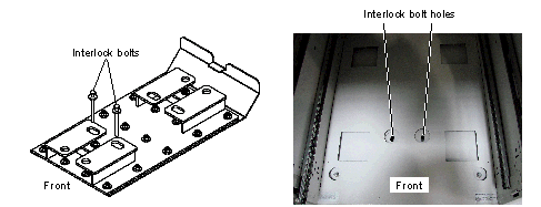
Engage the DM to the Mount
Follow the steps below to engage the DM to the OSHPD floor mount:
Unlock the lower drawer assembly and remove the necessary bottom drawer(s) by disengaging them from the slides (do not remove the entire drawer assembly). Place the drawer(s) on a flat workspace so they cannot be damaged.
Push the module back and into position on the floor mount until the module reaches the stop point on the mount.
Place the interlock bolts through the two holes in the bottom of the module and into the floor mount slots. If necessary, tap the interlock bolts with a hammer to ensure that the interlock bolts are completely through the holes and flush to the surface below the module floor.
Installing an SCM Cabinet Base
If the module does not have a pre-installed base, install the base as follows:
Carefully lay the cabinet on its back, being careful not to damage the cable.
Fully extend the front leveler feet outward.
Position the base flush with the back of the cabinet.
Secure the base to the bottom of the cabinet with the eight sheet metal screws supplied with the base kit.
Floor Standing for Non-Seismic Locations
The DM and SCM have casters and leveling feet unless they are to be mounted on top of another module. Roll the module into position and lower the leveling feet until they support the entire weight of the module.
 This equipment can tip over and cause injury if the leveling feet are not properly adjusted. Fully extend front leveling feet prior to stocking or using this equipment.
 Only qualified ABTG authorized service personnel may move and install a module. Do not remove the liability label on the top door window of a cabinet until specifically instructed to do so. Cabinets that are being moved can be tilted over and cause serious injury and damage.

Countertop Mounting for Non-Seismic Locations
Parts and Kits
See Countertop Mounting Kits—Non-seismic lists the modules and kit part numbers that must be used to mount a module on a countertop. The method of mounting a UDM, CDM, or SCM to a countertop is identical except for the screw lengths available. The UDM kit has one mounting screw length. The CDM/SCM kit has five different screw lengths to accommodate different countertop thicknesses. Select the proper screw length so that the screws do not interfere with drawer operation (CDM) or shelf operation (SCM).
Mounting a UDM on a Countertop
Use the template supplied in the installation kit to locate the holes in the countertop with relation to the edges of the UDM. Mounting a UDM on a countertop requires access beneath the counter to allow threading the mounting screws up from beneath the counter. Refer to the steps printed on the template.
Security bit (19-038759-000A) for 1/4” socket driver

Do not attempt to install this equipment without assistance.
The supplied template has markings that indicate the UDM footprint. Follow the directions on the template for locating the four mounting holes on the countertop. Outline each hole and center punch their approximate centers.
Drill four mounting holes. Use a 1/8” drill bit to make starter holes and a 3/8” bit for the final hole diameter. Drill the four mounting holes through the top.
Depending on the IBcable routing, it may be necessary to drill a 1-1/2” (38mm) diameter hole in the countertop to achieve a direct path to the connector panel on the module.


Do not attempt to install this equipment without assistance.
Position the UDM on the countertop with the help of an assistant. The four threaded inserts on the bottom of the UDM must line up with the four drilled holes in the countertop. The drilled holes in the countertop are large enough to allow some adjustment.
Insert the four supplied security screws (with washers) through the underside of the countertop and into the UDM threaded inserts.
Do not over-tighten the screws because the inserts can break loose or strip.
Mounting a CDM on a Countertop
Use the template supplied in the installation kit to locate the holes in the countertop with relation to the edges of the CDM. Mounting a CDM on a countertop requires access beneath the counter to allow threading the mounting screws up from beneath the counter. Refer to the steps printed on the template.
|
1/8” and 3/8” drill bits (starter holes) |
The supplied template has markings that indicate the CDM footprint. Follow the directions on the template for locating the four mounting holes on the countertop. Outline each hole and center punch their approximate centers.
Drill four mounting holes. Use a 1/8” drill bit to make starter holes and a 3/8” bit for the final hole diameter. Drill the four mounting holes through the top.
Depending on the IB cable routing, it may be necessary to drill a 1-1/2” (38mm) diameter hole in the countertop to achieve a direct path to the connector panel on the module.

Do not attempt to install this equipment without assistance.
Position the CDM on the countertop with the help of an assistant. The four threaded inserts on the bottom of the CDM must line up with the four drilled holes in the countertop. The drilled holes in the countertop are large enough to allow some adjustment.
Insert the four supplied security screws (with washers) through the underside of the countertop and into the CDM threaded inserts.
Do not over-tighten the screws because the inserts can break loose or strip.
 Before proceeding with installation, examine the kit supplied template to determine the correct screw length for the counter thickness. A screw that is too long will interfere with drawer movement. If all the screws are too long, use the screws closest to the size you need and add extra washers under the countertop to fill in.
Mounting an SCM on a Countertop
Use the template supplied in the installation kit to locate the holes in the countertop with relation to the edges of the SCM. Mounting an SCM on a countertop requires access beneath the counter to allow threading the mounting screws up from beneath the counter. Refer to the steps printed on the template.
The supplied template has markings that indicate the SCM footprint. Follow the directions on the template for locating the four mounting holes on the countertop. Outline each hole and center punch their approximate centers.
Drill four mounting holes. Use a 1/8” drill bit to make starter holes and a 3/8” bit for the final hole diameter. Drill the four mounting holes through the top.
Consider the lock cable route to the stand-alone ELC. Depending on the routing, it may be necessary to drill a hole in the countertop to create a path to the ELC.

Do not attempt to install this equipment without assistance.
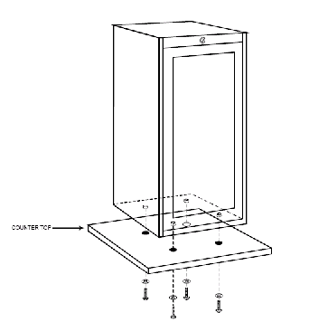
Position the SCM on the countertop with the help of an assistant. The four threaded inserts on the bottom of the SCM must line up with the four drilled holes in the countertop. The drilled holes in the countertop are large enough to allow some adjustment.
Insert the four supplied security screws (with washers) through the underside of the countertop and into the SCM threaded inserts. A chart is provided on the template to determine the exact screw size for counter thickness.
Do not over-tighten the screws because the inserts can break loose or strip.
Countertop Mounting for Seismic Locations
Procedure
Use the template included with the kit prepare the surface of the countertop, then install the countertop mount.
Prepare the Counter Surface
Follow this procedure for each counter mount kit. Ensure that the mounts are located so that the cabinets are adjacent to each other and properly aligned.
Ensure that all shelves are securely positioned and clear of all materials.
Ensure that there is adequate room beneath the counter to secure the fasteners after installation.
Identify any electrical wall outlets or mounted surge protectors that must be taken into account when positioning the mount.
Refer to the notations on the installation template and cut the template according to the designed placement of the mount kit.
Align the installation template on the counter, noting any wall obstructions that may need to be taken into account; tape the template to the work surface.
Use the centerline mark to position the installation template.
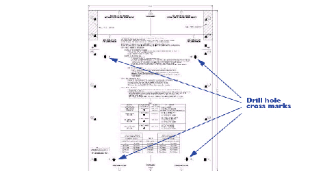
Mark the drill locations on the counter using the four hole cross marks on the template.
Install the Mount
Position the module on the countertop, aligning the internally threaded fasteners on the bottom of the module with the four holes in the countertop.
Insert a double threaded rod into one of the of the holes, small threads first, and hand tighten the rod into the threads on the bottom of the module.
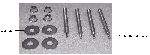
Module-to-module Mounting
Most kinds of modules can be mounted on top of another module, as shown in the following table:
Parts and Kits
The same module kits and part numbers are used to mount modules to modules as are used for mounting a module to a countertop:
Mounting one Module on Top of Another
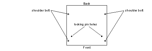
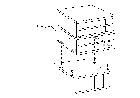
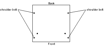
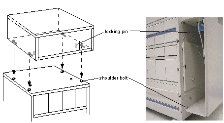
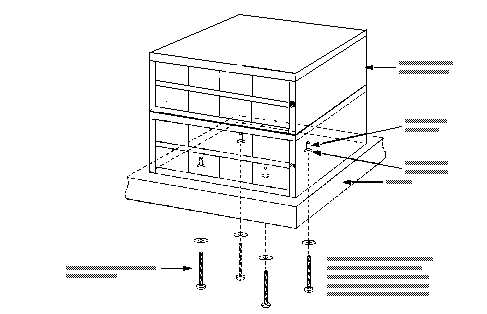
One module can be mounted on top another with the use of four shoulder bolts, illustrated below.

Flat blade screwdriver.
It is not necessary to remove any drawers from either cabinet.
The bottoms of MedSelect modules are equipped with spring-loaded pins and keyhole slots that facilitate mounting on top of another module. To top mount one module to another, perform the following steps:
Remove the six adhesive labels from the top surface of the bottom module to expose the six holes.

Mounting an ELM
Install an ELM when a customer needs controlled access to equipment other than a Tower or MedSelect module. Typically, the ELM is used to secure access to a refrigerator, drawer, or cabinet. In this context, “cabinet” does not mean a module or tower cabinet, but rather a structure such as a kitchen cabinet in use at the facility.
Parts and Kits
See ELM Mounting Kits shows the kits available for mounting an ELM:
The adhesive plate is used to mount the ELM body to the side of a refrigerator without drilling holes or using screws. This may be necessary when it is not possible to confirm the presence of refrigeration lines in the side of a refrigerator.
Refer to your installation documentation to determine whether an ELM is to be installed, and where, then follow the appropriate procedure:
The ELM mounting kit comes with a reinforcement bracket and two #8 Nylock nuts that are to be used whenever the outside edge of the refrigerator door is inset from the side of the refrigerator. The bracket is not used when the edge of the refrigerator door is flush with the side of the refrigerator, cabinet or drawer.
Apply the following considerations when mounting an ELM on a refrigerator:
The door must not sag when opened.
The door width or swing radius must be 2’ (610 mm) or greater.
Cabinet doors and drawers must be 1-1/2” (38 mm) maximum from outside edge of cabinet or drawer housing.
Apply the following considerations when mounting an ELM on a cabinet or drawer:
The door must not sag when opened.
For wood or composite cabinets, self-tapping screws are recommended.
The door width or swing radius must be 2’ (610 mm) or greater.
Wood cabinets must be 1/2” (13 mm) thick or greater.
Steel cabinets must be 18 gauge (0.48” or 1.214 mm) or greater.
Cabinet doors and drawers must be 1-1/2” (38 mm) maximum from outside edge of cabinet or drawer housing.
Mounting an ELM
Side Mounting: The best installation point for the locking mechanism and strike bracket is the vertical center of the unit. It is recommended, especially on units greater than 36” (0.9m) tall, that the mechanism be mounted as close to the vertical center as possible for maximum security. The template is still useful in this type of installation by using the top and/or bottom reference lines as a level reference.
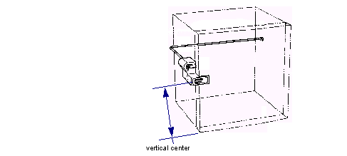
Follow the set of instructions appropriate to the method you will use to secure the ELM to the refrigerator:
See Mounting an ELM with Screws
See Mounting an ELM on a Refrigerator with an Adhesive Plate
Mounting an ELM with Screws
Locate the mounting holes for the locking mechanism with the supplied template. The template also includes installation information.

When drilling holes, do not penetrate deeper than 3/16”. Many units have refrigerant lines running through their walls.
1/8” drill bit with depth gauge
Bit for cover security screws (29-013205-000A)
Bit for locking mechanism and strike bracket security screws (19-038759-000A)
This procedure consists of the following steps, each of which is covered below:
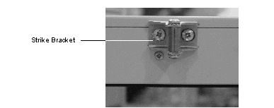
Mounting the Strike Bracket on a Door Edge that is Flush with the Refrigerator/Cabinet/Drawer Side
Position the bracket on the door and mark its two mounting holes on the door edge (the four front holes are not determined yet).
Observe the template orientation for the right and left handle doors (see notation on template).
Make sure the bracket is square with the door and is level.
Slightly bend the bracket for a snug fit around a curved door.
Drill the two 1/8” (3mm) holes with depth gauge on the door edge, but do not mount the strike bracket.
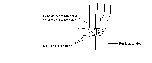
Place the template against the side of the refrigerator/cabinet/drawer and match the door edge strike hole markings with those of the template. Tape the template in position making sure that the reference lines are either level or aligned with the top/bottom edge.
Mark the holes as shown in See Marking Template Holes on a Refrigerator/Cabinet/Drawer.
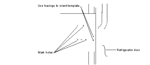
Use a 1/8” drill bit and depth gauge to drill the four holes in the indicated locations on the template.
Mount the strike bracket to the door edge using two supplied security screws. Be sure it remains level and snug before tightening the screws as shown in See Mounting Strike Bracket on a Refrigerator/Cabinet/Drawer Door.
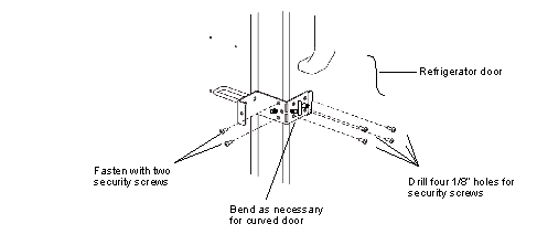
Mounting the Strike Bracket on a Door Edge that is Inset From the Refrigerator/Cabinet/Drawer Side
Position the bracket on the door and mark its two holes on the door edge (the four front holes are not determined yet).
Observe the template orientation for the right and left handle doors (see notation on template).
Make sure the bracket is square with the door and is level.
Slightly bend the bracket for a snug fit around a curved refrigerator door.
There are six possible locations for the front strike screws (including the ends of the slot). Mark the four positions closest to the edge of the door that can be drilled.
Drill the four 1/8” (3mm) holes with depth gauge on the door, but do not mount the strike bracket.
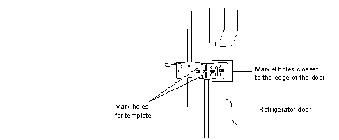
Marking Strike Bracket Holes on a Refrigerator/Cabinet/Drawer Door
Mark the template holes. Refer to steps 5 and 6 and See Marking Template Holes on a Refrigerator/Cabinet/Drawer (Marking Template Holes) in See Mounting the Strike Bracket on a Door Edge that is Flush with the Refrigerator/Cabinet/Drawer Side.
Use the 1/8” drill bit to drill the four strike bracket holes.
Place the reinforcement bracket over the strike and secure with two #8 Nylock nuts.
Secure the strike bracket to the door front with four security screws.
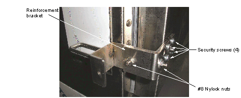
Install the strike bracket cover using the Phillips screws. Do not over tighten. Apply the top and two side cover labels.
Install the strike cover. Refer to step 12 and See Installing Strike Cover (Installing Strike Cover) in See Mounting the Strike Bracket on a Door Edge that is Flush with the Refrigerator/Cabinet/Drawer Side.
Mount the Lock Latch
Mount the lock body to the side of the refrigerator/cabinet/drawer by first installing the bottom two security screws.
Install the top two security screws. Do not completely tighten the screws.
Once the lock body is secured in place, manually disengage the main latch and rotate it counterclockwise until it is horizontal as shown in See Disengaging Main Latch.
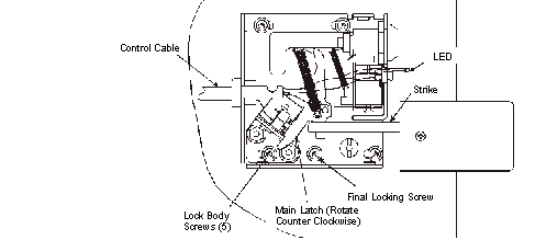
Close the door to check that the forward edge of the strike engages smoothly with the main latch while maintaining good contact when locked.
Manually disengage the latch and open the door. Open and close the door several times to be sure positive latching occurs. The lock body holes are slotted to allow for some positioning adjustment.
Use the 1/8” drill bit with depth gauge to drill the remaining hole for the lock body.
Install the final security screw. This screw permanently fixes the unit in place so be sure all adjustments are made before drilling this hole.
Tighten the remaining security screws on the locking mechanism.
Neatly route the lock cable along the refrigerator side and secure in place with general purpose adhesive back tie straps or a wire molding. These items are not supplied because of the large number of configurations for this device.
If the ELM has an LED in the cover, then place the LED locking ring (black ring) over the LED and its wires.
Secure the cover to the lock body using the five security screws.
Mounting an ELM on a Refrigerator with an Adhesive Plate
Use the adhesive plate to mount the ELM body to the side of a refrigerator without drilling holes or using screws. The strike is still mounted to the door with screws.
This procedure consists of the following steps:
Mount the Strike Bracket
Attach the strike to the door by following the steps in See Mounting the Strike Bracket on a Door Edge that is Flush with the Refrigerator/Cabinet/Drawer Side or See Mounting the Strike Bracket on a Door Edge that is Inset From the Refrigerator/Cabinet/Drawer Side.
Mount the Lock Body
Clean the refrigerator where the body will be mounted.
Secure the adhesive plate to the body using four flange nuts. Ensure the threaded studs on the adhesive plate are centered in the slots of the body before tightening the flange nuts.
Locate the body on refrigerator vertically and horizontally using the strike as a reference.
The strike should engage the latch in the body so that in the closed position the switches are fully engaged. Leave a small amount of clearance between the latch and stop. See See Positioning ELM Body.
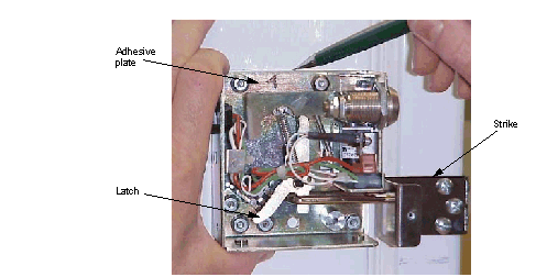
Mark the four sides of the adhesive plate on the refrigerator with a pencil.
Remove the adhesive backing from the adhesive plate.
Carefully locate and secure the body to the refrigerator.
Check the actuation of the strike and latch. If the latch does not fully engage the switch or if it forced against the stop then loosen the flange nuts, reposition the body and re-secure the flange nuts.
Install the ELC
Route the cable of the locking mechanism assembly to the ELC location.
If an Electronic Lock Controller has not already been installed, install one as described in See Mounting an ELC on a Wall, Counter or Module.
Remove the cover from the ELC.
Connect the IDC cable connector to the required CCA port. There are eight ports available, labeled J1 through J8.
Clearing a Premature Latching Condition on an ELM Locking Mechanism
This condition can occur when the strike does not freely rotate or it has been activated by something other than the strike bracket. It may also occur if the door/drawer (that the strike bracket is mounted to) sags when opened. If this is the case, the door should be fixed by the customer to prevent this problem.
Needle nose pliers
Perform the following procedure to clear a premature latching condition on the ELM locking mechanism:
Manually unlock the unit using the key lock. Once the unit is unlocked, the key cannot be removed.
Insert pliers into side opening of the locking mechanism where the strike enters the unit.
Locate strike and clamp it with the pliers. Rotate the strike towards the opening by pulling the pliers out of the opening in the locking mechanism until the strike reaches its limit and stops.
Manually open and close the door several times to be sure the problem does not exist.
Security Cable
This kit contains one lag bolt, one toggle bolt, and the security cable. The security cable attaches the module to the wall and ensures the DM or SCM cannot be moved from its designated location.
Provide enough slack to allow for service and mount high enough to avoid interference with casters, other components, etc.
Determine from the project manager the selected security method, which may require the use of another fastener supplied by the customer. Securing the cable with another fastener may vary from the standard attachment procedure using the supplied parts.
Perform the following procedure when using the supplied parts:
Drill a hole in the wall large enough to accommodate the toggle bolt.
Push the toggle bolt though until the levers spring open.
Thread the 1/4-20 x 5/8 screw into the nut on the inside of the back of the module and tighten the screw.
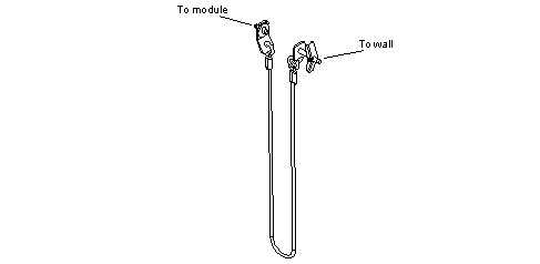
Install in Final Location: Tower Modules
The instructions supplied with kits supersede any installation information provided in this manual.
Always use the template supplied with the mounting kit. The template contains detailed instructions for all mounting configurations so take the time to read the instructions
before drilling holes
.
Instructions on the installation worksheet supersede any information provided in this manual. Fill out the installation worksheet provided with each tower module before installing any equipment. This records all important configuration and key assignment information. Follow any other instructions listed on this worksheet.
Before securing tower in place, make all IB cable connections to its rear connectors. Refer to See IB Cable Installation.
 Only qualified ABTG authorized service personnel may move and install a tower. Do not remove the liability label on the top door window of a cabinet until specifically instructed to do so. Cabinets that are being moved can be tilted over and cause serious injury and damage.
 Do not attempt to move the tower module without assistance. Ensure that all shelves are securely positioned and all doors are securely closed and locked before positioning the tower. Be aware of site personnel and your surroundings when using power tools.
When installing a tower module, provide these clearances:
Back of cabinet to wall: 1–3” (25-76 mm)
Wall to front of cabinet when pulled forward for light panel access: 46-1/2” (1.181 m)
Right side of cabinet to wall, to allow for light panel access: minimum 4” (102 mm)
Back of cabinet to front of open door: 53-7/8” (1.369 m)
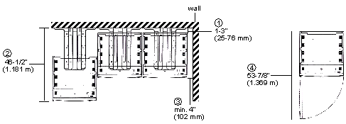
Tower module mounting methods vary depending on whether the tower is being installed in a seismic area or not. Refer to the Installation Worksheet, then follow the appropriate set of instructions below:
For seismic locations, including the state of California, follow the instructions in See Permanent Mount Installation for Seismic Locations.
Permanent Mount Installation for Non-seismic Locations
A permanent mount is shipped with each tower module, and is owned by the customer. It is assumed the selected locations will allow for clearance of door swing radius. The mount may be hanging from the underside of the tower for ease of transportation.
Parts and Kits
A permanent mount can be secured to a floor or wall; the same kit is used in either case.
When secured to a floor, the mount uses expansion anchors. When secured to a wall, the mount uses lag screws (for wood studs) or lag screws and toggles (for metal studs and unsupported wall sections). The permanent mount is supplied with a complement of hardware for floor and variations of wall mounting (wood and metal stud).
Refer to the Installation Worksheet, then follow the appropriate set of instructions:
Anchoring Permanent Mount to the Floor
The permanent floor mount does not need to be against a wall to be effective. The mount can be attached to a concrete floor with six anchors and can be attached anywhere on the floor. However, the anchor hole for a concrete floor can be no closer than 3-1/8” from a drop off edge. Otherwise, there is a danger of the concrete cracking from the stress placed on the anchor and therefore, a possible unsafe condition.
The design of intended mounting surfaces, including the verification of their structural integrity, is the customer's responsibility. The customer should have inspected the structural integrity of the floor before installation. The standard anchors supplied with the floor mounting kits are acceptable for certain concrete conditions. If custom floor mounting anchors are necessary, they will be listed in the Installation Planning Documentation. If concrete issues are discovered during the installation, notify the customer contact immediately.
|
Anchor setting tool from service kit Recommended: Torque wrench that can apply 11 ft-lb (14.9 N·m) |
Use the permanent floor mount as a template to mark the six anchor hole locations on the floor.
Drill the six holes to a depth of 1-9/16” (using depth gauge) with a 1/2” masonry bit.
Clean out the hole and surrounding area with shop vacuum.
Insert a supplied 3/8” expansion anchor into each hole.
Use the service kit anchor setting tool to drive the center insert and expand the anchor until anchor setting tool meets top of anchor.
Secure the mount to the expansion anchors using the supplied 3/8”-16 x 1.0 hex head bolts and washers (use a 9/16” socket and ratchet). Torque the anchor bolt to 11 ft-lb. (14.9 N·m).
Proceed to See Engaging the Cabinet in the Permanent Mount.
Anchoring Permanent Mount to a Wall
When anchoring the permanent floor mount to a wall, additional anchoring to the floor is not needed. Before proceeding with the procedure, read the warning and caution statements below.
Be certain that the facility has 16-inch or 24-inch on-center wall studding. The permanent floor mount is designed with pre-drilled holes to be mounted to a wall with this spacing between studs.
 Before drilling holes into a wall, consult lab administrator and Installation Planning Documentation supplied by the project manager to determine that there are no electric lines, gas supply lines, or other utilities behind the wall in the immediate area of work. Also, be certain that drilling holes will not affect the protection provided by lead-lined walls in rooms containing x-ray or fluoroscopic equipment.
 In some states and localities, it is required to reinforce the wall when installing equipment attached to walls. Be sure to install the permanent floor mount according to these requirements. Refer to the installation planning documentation.
Determine the wall studding locations (with stud finder) and type (wood or metal).
The permanent floor mount is designed to accommodate cabinets that are mounted side-by-side with the least amount of space between them for a wall with 16" or 24" on center studding. Determine how many cabinets will be used side-by-side and position their permanent floor mounts according to the following anchoring criteria (see See Permanent Floor Mount Wall Mounting Attachment Arrangements):
The columns of pre-drilled holes in the vertical plate portion of the mount are spaced to fall on the center of at least one stud. Two columns of holes for two of the side-by-side mounts will fall on adjacent studs, and only one column of holes for the other mount will fall on a stud. If more cabinets are banked, then the hole pattern will repeat.
The column of holes that match wood studs use the supplied lag bolts; metal studs use toggle bolts. Always use all three holes, with anchors, of a column.
When only one column of holes match a stud, toggles are used to secure the mount to the wall at three holes on each side of the column for a total of nine. See Permanent Floor Mount Wall Mounting Attachment Arrangements.
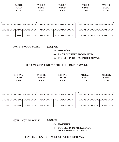
Find and mark the center of each wall stud by drilling several small finder holes to locate both edges of a stud. Always determine the inside edge of a stud first. Use the markings to verify that the studs are accurately set on 16" or 24" centers.
Use the center line of one of the end studs (leftmost or rightmost cabinet position) as a reference. Then use the vertical plate of the permanent floor mount as a template to mark off the anchor hole locations on the wall for all cabinet positions.
Proceed to the appropriate subparagraph below, depending on whether the studding is metal or wood.
If the wall has metal studs and unsupported wall board (toggle bolts)
Determine the center for each hole as closely as possible. Drill a 3/16” pilot hole all the way through the wall board and metal stud for each hole.
Drill a 7/16” hole to enlarge each hole to accept the 3/4” bit in the next step.
Drill the final 3/4” hole sizes.
Loosely attach all the bolts, washers, and toggles to the wall bracket before placing the bracket against the wall. Do not thread the toggle screw too far into the toggle at this point; otherwise, the toggle will not completely pass into the open space behind the metal stud. If this occurs, it will not open up.
Position the permanent floor mount (with attached toggles) so that its mounting holes match those on the wall and press each toggle through the wall and inside the open space of the wall or metal stud.
Be certain that all toggles are completely inserted and free in the open space behind the wall or metal stud. This can be determined by trying to pull the toggle back out of the hole. Toggles are spring loaded and will open up in the open space.
Expand the top toggles first. Slowly open each toggle by tightening its screw. Be certain that the toggle flares along a stud. Once all the toggles are open, the permanent floor mount is secured to the wall and stud. Tighten each screw until snug. Check to see if the mount is pulling against the wall and its base is resting fully on the floor. When the position is correct, completely tighten all toggle screws.
Pull on the screw head to cause the toggle to tighten up. Use a straight edge or fashion a tool to help pull on the screw head while tightening the anchor.
Proceed to See Engaging the Cabinet in the Permanent Mount.
If the wall has wood studs and unsupported wall board (lag and toggle bolts)
Lag bolts are used for walls with wood studs and toggles are used for unsupported sections of wall board. Depending on the position of the permanent floor mount, additional fastening to unsupported wall will be required.
Determine the center of each hole as closely as possible. Drill a 3/16” pilot hole all the way through the wall board and into the wood stud for each hole. Where studs are located, these holes are pilot holes for the supplied lag bolts that are used to secure the permanent floor mount to the studs. For unsupported wall board (no studs), these holes must be enlarged to accept toggles.
For unsupported locations, drill a 7/16” hole to step up the diameter of each hole for accepting the 3/4” bit of the next step.
Drill the final 3/4” hole size for the unsupported locations. At the unsupported wall hole positions, loosely attach the toggles to the permanent floor mount, including the back up washers. Do not thread the toggle screws too far into the toggle at this point; otherwise, the toggle will not completely pass into the open space behind the metal stud. If this occurs, the toggle will not flair.
Position the permanent floor mount (with attached toggles) so that its mounting holes match those on the wall and press each toggle through the wall and inside the open space of the wall.
Be certain that all toggles are completely inserted and free in the open space behind the wall. This can be determined by trying to pull the toggle back out of the hole. Toggles are spring loaded and will open up in the open space.
Slowly open each toggle while checking to see if the mount is pulling against the wall and its base is resting fully on the floor. When the position is correct, completely tighten all toggle screws.
Use the lag bolts and washers to secure the wall permanent floor mount to wood studs. The lag bolts require a 1/2” socket. Back up each bolt head with a supplied washer. Tighten each bolt until snug.
Continue with See Engaging the Cabinet in the Permanent Mount below.
Engaging the Cabinet in the Permanent Mount
After completing installation of the permanent floor mount, the cabinet is ready to be moved into position over the mount.
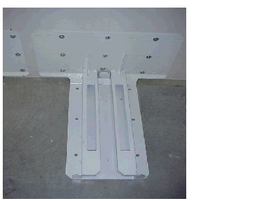
This shows a mount secured to a wall.
Install the cabinet onto the permanent floor mount by pushing the centered cabinet over the mount until it can go no further.
The cabinet can be moved one inch (1”) left or right from the center of the mount.
Install the 3/8”-16 x 3 ½” bolt from the mounting kit by dropping it into one of two holes at the inside rear of the cabinet.
The bolt drops into the hole and is not screwed down as a fastener. The bolt is simply used as a pin that drops within a confined area in the permanent floor mount. You may have to remove or extend one or more of the bottom shelves to access the hole. If the bolt does not line up with the first hole, use the other hole.
Close the bottom door and pull the cabinet forward and ensure that the cabinet cannot be pulled off the permanent floor mount. The cabinet does have some freedom of movement in all directions.
If the cabinet can be separated from the mount, then the pin is not engaged with the mount. Repeat See Install the 3/8”-16 x 3 ½” bolt from the mounting kit by dropping it into one of two holes at the inside rear of the cabinet. and See Close the bottom door and pull the cabinet forward and ensure that the cabinet cannot be pulled off the permanent floor mount. The cabinet does have some freedom of movement in all directions. using the other hole for the bolt.
Engaging the Leveling Feet
Four leveling feet are provided on the bottom of the cabinet. Do not adjust the level of the cabinet until the cabinet is positioned in its final location over the permanent mount. Typically, the final location is level and the tower module requires no additional adjustment. The front two leveling feet are only extended to the floor to prevent caster motion of the cabinet over the floor mount. The rear two feet are typically left retracted.
The front two leveling feet can be adjusted with an open end wrench. However, the rear two feet leveling adjustment must be accessed from the inside rear of the cabinet. One or more bottom shelves require removal to make any leveling adjustment. The adjustment is made with a standard 3/8” socket. A short extension may be helpful.
Permanent Mount Installation for Seismic Locations
This topic provides instructions for assembling and installing the mounting kit for the tower module that is compliant with the Office of Statewide Health Planning and Development (OSHPD) regulations for the State of California, covering the California Building Code (CBC) and the International Conference of Building Officials (ICBO).
The mounting plate ships with the Tower. It passes all California seismic requirements defined by OSHPD. The plate provides equivalent UL safety ratings, and tip avoidance, along with ease of installation using built-in, notched, centerline indicators.
This design ensures that the tower module is securely mounted through floor anchors into approved concrete substrata. However, the structural integrity of the concrete substrate of the floor must be confirmed by the customer before installation can take place. The mounting design does not require access under the floor for additional hardware and allows mounting in all situations, including ground level or non-accessible lower floors.
Parts and Kits
The tables below provide the part numbers, mounting kit descriptions, and the special tools required to mount the tower module according to OSHPD regulations for the State of California
Procedure
|
1-1/8” deep well socket and wrench |
This procedure consists of the following steps, each of which is covered below:
Coordinate with the OSHPD compliance officer
Install the Tower Module OSHPD floor mount kit
Install the mount and obtain compliance approval
Engage the Tower Module to the mount
Show the customer how to remove the interlock bolts
Coordinate with the OSHPD Compliance Officer
Contact the OSHPD compliance officer and obtain permission to start the installation procedure.
You will also need the compliance officer’s approval during this procedure.
Install the Tower Module OSHPD Floor Mount Kit
The floor mount is installed using the supplied anchors, washers, plate washers, and nuts.
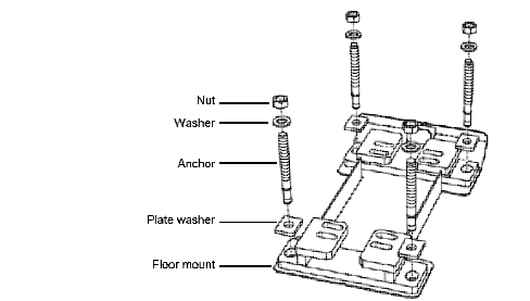
Floor Mount for Seismic Locations.
This procedure covers a single tower module and floor mount kit. If you install additional towers and kits, follow these procedures for each installation. Ensure that the mounts are located properly so the cabinets will be adjacent to each other and properly aligned. Install the kit as follows:
Identify any electrical wall outlets or mounted surge protectors that must be taken into account when positioning the tower module.
Identify the centerline of the tower module and mark the floor or wall with the tower’s centerline.
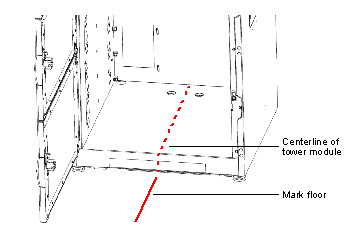
Refer to the notations on the installation template and cut the installation template according to the desired placement of the cabinet from the wall.
Slide the installation template on the floor until it is touching the wall, noting any unusual wall obstructions that may also need to be taken into account.
For multiple tower module installations, allow minimal space between towers. A tower is approximately 28 inches wide. Consider using a spacing of 28-1/8” for each tower to locate the centerline position and place the mount for each tower module.
Position the installation template according to the centerline mark and then carefully mark the drill locations on the floor using the four hole cross marks on the template for the drill locations.
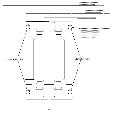
Install the Mount and Obtain Compliance Approval
Use a heavy-duty power drill and 1/4” drill bit to drill a pilot hole at each of the four anchor hole locations. Increase the bit size in 1/8” increments to 3/4”, drilling to a minimum depth of 4” but not beyond the depth where the bit breaks through the floor.
Clean the anchor holes with a shop vacuum or compressed air.
Hammer the Hilti Kwik Bolt 3 Expansion Anchors into the holes so that at least 3-1/4” of each bolt is in the hole.
Position the floor mount over the expansion anchors. Ensure that the mount is correctly positioned, facing outward, so you can slide the tower module unimpeded over the mount.
For ease of placement, the mount has built-in, notched, centerline indicators. These indicators should be used to position the mount by matching them to the lines drawn from the centerline of the installation template. Use the mount to place towers either 1” or 2-1/2” from the wall to provide clearance for cabling, 3-prong wall outlets, and surge protectors.
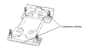
Place the washers and the nuts over each expansion anchor. Tighten the nuts to 150 foot pounds.
Request that the OSHPD compliance officer test the tightened nuts on each expansion anchor according to the required test schedule.
If approved, move to the next step.
If not approved, ask the OSHPD compliance officer to identify the reason for non-compliance. Then correct the problem before moving to the next step, or notify your supervisor.
If necessary, install spacer blocks at the back of the tower module.
Installing Alignment Spacer Blocks
Two styrofoam blocks are provided for each tower module. These spacers help to ensure that adjacent towers remain aligned during use.
The instructions below include guidelines for locating the spacers on the back of each tower module. Use your judgment for placement of the spacers. Take into consideration walls, wall trim pieces, and other elements that change the distance between the wall and equipment so that when the spacers are placed on the back of the equipment and the equipment is moved toward the wall, the front of each tower module lines up.
Check the wall against which each tower module will be located.
Note any obstacles or elements that protrude from the walls to determine the vertical location of the blocks on the back of each tower module to ensure that the equipment lines up after it is moved against the wall.
Clean the surfaces on the back of the tower module where the blocks will be placed with alcohol and a cloth.
Remove the paper strip that protects the self-adhesive area on the back of the styrofoam spacer block.
Place a styrofoam spacer in its proper location on each side of the back of the tower module.
Move the tower module towards the wall until the spacers touch the wall, aligning the adjacent towers horizontally.
Engage the Tower to the Mount
Engage the tower module to the floor mount by removing the bottom shelf within the module to gain access to the interlock bolt hole locations for the mount.
Unlock and open the bottom door and remove the fixed shelf by lifting it off the side inserts or remove the sliding shelf by disengaging it from its slides. Place the shelf on a flat workspace so that the shelf cannot be damaged.
Close the bottom door and push the tower module back and into position on the floor mount until the tower module either contacts the wall with the foam blocks or until it reaches the stop point on the mount.
Open the bottom door and place the interlock bolts through the back holes in the tower and into the floor mount slots. If necessary, tap the interlock bolts with a hammer to ensure that the interlock bolts are completely through the holes and flush to the surface below the tower floor.
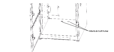
Re-install the bottom shelf and close and lock all doors on the tower module.
Install in Final Location: Display Terminal
The instructions supplied with kits supersede any installation information provided in this manual.
This chapter contains information and procedures for the MedSelect System and SupplySelect System. Not all information or procedures are entirely applicable to each system. The installer must determine from the Installation Planning Documentation which information or procedure is applicable. The documentation is obtained from the project manager.
The order of presented DT installation information and procedures is the recommended sequence of installation.
Refer to the product cut sheets for detailed layout information. The sheets should be on hand for the installation.
The overall process of installing the DT follows these steps:
If you are installing a Centrack system, note that the procedure for mounting a hub is identical to the procedure for mounting a repeater.
See Optional Equipment Installation
See Wireless scanner (SupplySelect and Centrack)
See DT Mounting Kits lists all the mounting kits associated with the DT installation. The installation procedures that follow do not explicitly describe the installation of each kit, but rather provides general information and procedures applicable to all kits. However, the procedures will explicitly note kit installation details where needed.
DT-UI Installation
An extruded aluminum channel is used in all configurations except module-on-counter, as the means of attaching the DT-UI to its mounting surface. An interface adapter is used to attach the DT-UI to the channel. There are two adapters for mounting a DT-UI in one of the following ways:
Directly fixed to the channel via a flush mount assembly (flush mount)
Via an extended mount assembly (extended mount), which suspends the DT-UI on a pivot.
In either case, the channel is mounted first, then the DT-UI is attached to the channel.
Installing the Channel
Refer to See DT Mounting Kits for the limitations for mounting the channel. These limitations must be observed to assure a safe and reliable support for the DT-UI.
The hardware and hole layout for the channel is shown in See Channel Hardware and Mounting Hole Layout.
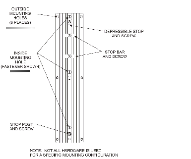
The channel hardware plus mounting hardware is included in the mounting kits. These kits have parts to accommodate all mounting variations and may include spare fasteners.
Note that the channel mounting hole layout is not symmetrical. Thus, you must consider the left-right or top-bottom orientation of the channel when attaching hardware. The DT-UI flush or extended mounts always slide onto the channel at the depressible stop end.
 If the wrong knockouts are punched or the wrong hole locations are drilled for the intended channel orientation, there is no corrective cover-up procedure provided in this document.
Be sure that you are removing the correct knockouts or drilling holes in the specified locations on the cabinet.
Refer to your installation documentation to determine which kind of mounting is required, then follow the appropriate procedure:
See Mounting the Channel to a Wall
Mounting the Channel to a Wall
The channel must be mounted to studs of a wall board, which can support the DT weight. Hardware is included for mounting the channel on either the unsupported sections (use toggles) or supported sections (use screws or toggles, depending on wood or metal studs) of wall board.
Unsupported walls may be reinforced by the customer to provide the same support as studs. Check the installation planning documentation to determine whether this has been done.
Before drilling into a wall, know what is behind and inside the wall at the intended location. Obtain mounting location from installation site layout plans and permission to drill holes into the wall.
 Always make sure that the channel fasteners are installed along the center line of a stud. Also, never use sheet metal screws for attaching the channel to metal studs. Always use the toggle wings for metal studs. Otherwise, the weight of the DT-UI may cause the channel to pull off the wall and cause serious injury.
3/8” electric drill and 1/8” starter bit
11/16” drill bit (for metal studs)
Carpenter's level and Stud finder
Determine the DT-UI mounting location and its desired height from floor. This information must be obtained from the installation planning documentation.
Locate the wall stud using a stud finder at the height determined from the site plan.
Determine the hardware required for mounting the channel.
Four fasteners are required to mount the channel. If you are mounting the channel to wood studs, use the supplied high tensile screws. If you are mounting the channel to metal studs, use the supplied toggles. The toggles require an 11/16” hole.
Make sure that the anchors are installed along the center line of a wood or metal stud. If mounting to an unsupported wall board surface, make sure the mounting holes are vertical with a carpenter’s level.
Install the channel with the selected hardware in the proper orientation.
The supplied plastic stop post must always be used on the bottom of a vertically mounted channel for safety, and a depressible stop is always at the other end of a vertically or horizontally mounted channel (see See Channel Hardware and Mounting Hole Layout).
Refer to the following diagram (See DT-UI Channel to Stud Mounting and DT-CPU to Stud Mounting Diagram) for component to wall stud(s) mounting:
Mounting Channel Horizontally to a Wall
The method of mounting a channel horizontally to a wall is shown in See Mounting Channel Horizontally to a Wall.
Attach the stop post and the depressible stop to the channel. The raised end of the depressible stop must point towards the center of the channel.
Determine the side that the DT-UI will slide onto the channel from the installation planning documentation. This will be the side having the depressible stop.
Use the channel as a template and mark off mounting holes at 16" centers on each end. Be sure to level the channel first.
If there are wood studs, drill a starter hole with a 1/8” bit. If there are metal studs, drill a hole with the 11/16” bit.
Attach the channel to hole locations using the proper hardware for wood (screws) or metal studs (toggles).
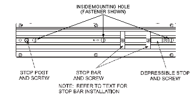
Mounting Channel Vertically to a Wall

Be sure to use the stop post at the bottom of a vertically mounted channel. This stop will prevent the DT-UI mounting from dropping free from the channel should a stop bar come loose. The DT-UI weighs approximately 22 pounds (10 kg).
The method of mounting a channel vertically to a wall is shown in See Mounting Channel Vertically to a Wall.
Attach the stop post and the depressible stop to the channel. The raised end of the depressible stop must point towards the center of the channel.
Use the channel as a template and mark off mounting holes. Be sure to level the top of the channel first.
If there are wood studs, drill a small starter hole with a 1/8” bit. If there are metal studs, drill a hole with the 11/16” bit.
Attach the channel to hole locations using the proper hardware for wood or metal studs.
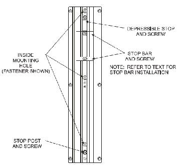
Mounting the Channel on a UDM or SCM
The method of mounting a channel horizontally to UDM and SCM cabinets is shown in See Mounting Channel on a UDM or SCM.
Attach the stop post and the depressible stop to the channel. The raised end of the depressible stop must point towards the center of the channel.
Remove the six plastic adhesive covers marked with an A for a horizontally mounted channel. Use the channel as a locator to be sure that the correct holes are used.
Attach the channel to holes using required quantity of screws.
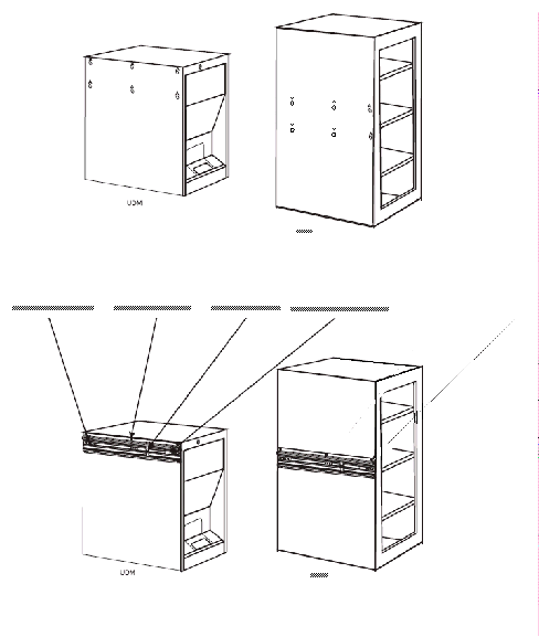
Mounting the Channel on a Tower

Be sure to use the stop post at the bottom of a vertically mounted channel. This stop will prevent the DT-UI mounting from dropping free from the channel should a stop bar come loose. The DT-UI weighs approximately 22 pounds (10 kg).

All six holes must be used to mount the channel to the cabinet. This is a requirement for left and right side panels of the cabinet.
The tower has holes on both sides to vertically mount the DT-UI channel.
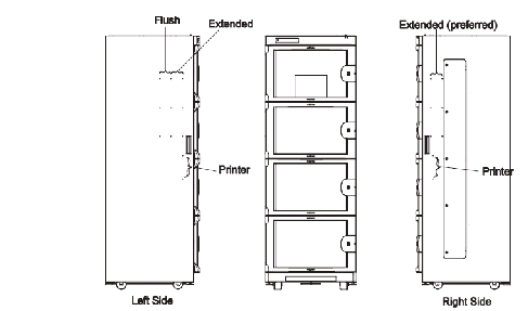
The left side panel has three columns of three holes. The front two columns of holes are for an extended mount; the rear two columns for a flush mount.
The right side panel has two columns of three holes. It is recommended that only an extended mount be used on this side. A flush mount can be used, but the DT-UI must be removed to change the light bulb (if the cabinet has interior lighting).
The two lower holes on both sides are not used to mount the channel (they are used to mount an optional printer).
Refer to See Mounting On the Side of a Tower Module for additional tower component location.
The two types of DT-UI mounts are shown below:
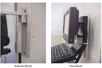
Hammer and 1/8” punch (cabinet hole knockout)
Attach the stop post and the depressible stop to the channel. The raised end of the depressible stop must point towards the center of the channel. In this orientation, the depressible stop is at the top.
Select the correct column of knockouts on the cabinet.
Installing the DT-UI Display Assembly
The procedures below assume that the channel has already been mounted according to methods under See Mounting the Channel to a Wall or See Mounting the Channel on a UDM or SCM or See Mounting the Channel on a Tower.
Either an extended mount kit or a flush mount kit is included with each DT-UI. There is no default mounting configuration. The constraints for mounting the DT-UI display assembly with either a flush mount or extended mount configuration are as follows:
Vertical and horizontal extended mount
Vertical and horizontal flush mount
The mounting kits include all necessary hardware for mounting the DT-UI to the channel. When using the supplied hardware keep these points in mind:
A cover plate is used on the back of the display support bracket to hide the flush mount adapter mounting holes when the pivot extension arm is used. This plate (including a fastener) is included in the kit.
A spacer plate is always used between the flush mount adapter and display support bracket for a flush mount configuration.
A stabilizer bracket is always used with a flush mount configuration.
A set of vendor's hardware is packaged with the channel. Not every item in this package is used for a mounting configuration.
If it is decided to swap an extended mount with a flush mount or vice versa on a vertical channel, the DT-UI height will not change because of the swap.
Proceed to one of the following procedures to mount the DT-UI:
Extended Mount
 Protect the screen, keyboard, and attached cable bundle from damage while installing hardware. Tape padding over the screen until work is completed. Do not to step on the cable bundle. Roll the bundle and tape it to the display support bracket as a precautionary measure. Temporarily use several small pieces of tape to secure the keyboard to its shelf on the display support bracket.
#2 Phillips head screwdriver
Go to the appropriate procedure to install the DT-UI assembly using an extended mount:
Mounting to a Vertical Channel
Install DT-UI extended mount to a vertical channel as follows:
Place the DT-UI on a work surface with its screen face down and protected with suitable padding.
Attach the extended mount to the top of the DT-UI support bracket using four screws.
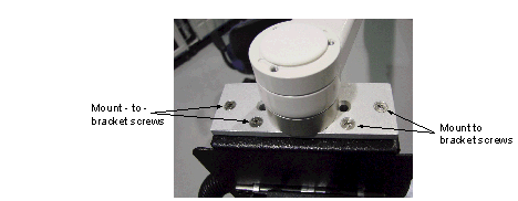
Attaching the Extended Mount to the Support Bracket
Attach cover plate over the flush mount adapter mounting location cutout on the rear of the display support bracket using one screw.
Check that the stop post and depressible stop are installed on the channel.
Install one stop bar and slide it to the bottom of the channel.
With assistance, install the extended mount slide into the channel. Drop the mount so its slide rests near the bottom of the channel. At this point readjust the stop bar for final DT-UI screen height (see installation planning documentation). Lock stop bar in place.
Install the second stop bar (top stop bar) and position the stop bar at the top of the extended mount. Lock the stop bar in place.
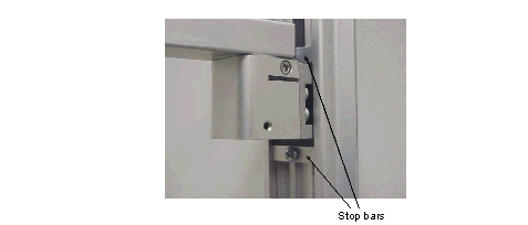
Mounting to a Horizontal Channel
Install DT-UI extended mount to a horizontal channel as follows:
Place the DT-UI on a work surface with its screen face down and protected.
Attach the extended mount to the top of the DT-UI support bracket using four screws see See Attaching the Extended Mount to the Support Bracket.
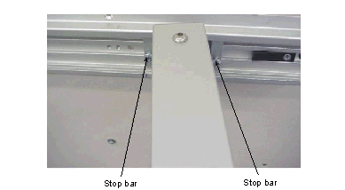
Attach the cover plate over the flush mount adapter mounting location cutout on the rear of the display support bracket using one screw.
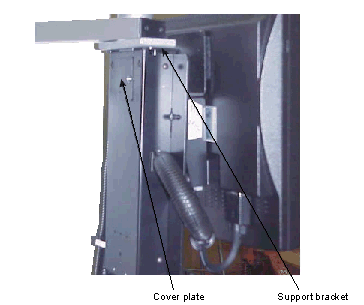
Install one stop bar by sliding it into the channel extrusion on the depressible stop side.
Position the stop bar at the desired horizontal position for the DT-UI screen. Lightly tighten it.
With assistance, install the DT-UI by pushing the slide of the extended mount into the channel extrusion from the depressible stop side. Push the slide along the extrusion of the channel to the desired horizontal position. At this point the stop bar should be readjusted for final DT-UI screen horizontal position. Lock stop bar in place.
Add the second stop bar against the pivot extension arm slide. Lock stop bar in place.
Setting Extended Mount Arm Swing Position and Pivot Friction
Complete the installation of the extended mount by fixing the position of the DT-UI for convenient and unobstructed access by the user. Also, the user should be able to rotate the DT-UI at its pivot point to allow for removal of glare from its screen.
After mounting the DT-UI to the channel with the extended mount, swing the DT-UI to the desired user position.
Set the DT-UI position by tightening 3/16” hex screw on the pivot block of the arm. There is a smaller hex screw on the block that should not be disturbed. This hex screw is used as a shaft lock and has been properly set by the manufacturer.
Adjust the two 5/32” hex screws on the front of the arm to set the friction at the pivot. Tighten these hex screws so that the DT-UI is snug at its pivot, but still can be easily positioned by hand. Never over tighten the hex screws to the point where the DT-UI cannot be pivoted without using both hands.
Flush Mount
#2 phillips head screwdriver
The flush mount can be used with a horizontal or vertical channel mounting orientation. This configuration is applicable to cabinet and wall mounting of a DT-UI.
 Never mount a DT-UI via an extended mount to a vertically mounted channel on a UDM or SCM cabinet. The side panels on these cabinets are not structurally strong enough to support this mounting configuration. Side panel damage will occur if a DT-UI is mounted in this manner.
Be sure to protect the screen, keyboard, and attached cable bundle from damage while installing hardware. Always tape a padding over the screen until all work is completed. Be careful not to step on the cable bundle. Roll the cable bundle and tape it to the display support bracket as a precautionary measure. Temporary use several small pieces of tape to secure the keyboard to its shelf on the display support bracket.
Mounting to a Vertical Channel
Install DT-UI flush mount to a vertical channel as follows:
Place the DT-UI on a work surface with its screen face-down and protected with suitable padding.
Attach the spacer plate and flush mount adapter to the rear of the display support bracket with the screws.
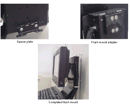
At the rear of the display support bracket, attach the stabilizer bracket in a horizontal orientation using two screws. Face the open side of the bracket out (i.e., away from the rear of DT-UI). This orientation is required so that the stabilizer bracket can be slid into the vertical channel extrusion.
Install a stop bar and slide it to the required height (see installation planning documentation) for the DT-UI screen. Just snug stop bar in place.
With assistance, install the DT-UI by first pushing the stabilizer bracket into the channel extrusion and then the flush mount. Drop the DT-UI so the stabilizer bar rests on the stop bar. At this point the stop bar should be readjusted for final DT-UI screen height. Lock stop bar in place.
Mounting to a Horizontal Channel
Install DT-UI flush mount to a horizontal channel as follows:
Place the DT-UI on a surface with its screen face down and protected with padding.
Attach the spacer plate and flush mount adapter to the rear of the display support bracket using four screws.
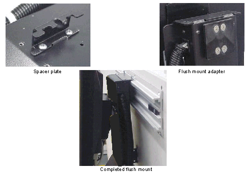
Mounting Flush Mount to Horizontal Channel
At the rear of the display support bracket, attach the stabilizer bracket vertically using two screws. Face the open side of the bracket towards the side with the stop post. This orientation is required if the bracket will be locked to a wall with a screw.
With assistance, install the DT-UI by pushing the flush mount into the channel extrusion from the depressible stop side. Push the flush mount adapter along the channel extrusion to the desired horizontal position.
If the stabilizer bracket is to be engaged with a screw head, mark off the point of contact (with DT-UI in the proper mounting position). Then move the DT-UI out of the way and install the screw (into wall with anchor, etc.). Then move the DT-UI back in place on the channel so that bracket locks onto the screw head.
Install the locking plate on top of the display support bracket with two screws.
Lock the DT-UI in position with the locking plate using two additional screws.
Make cable connections to the DT-CPU as described inSee Connecting DT-CPU Cables.
Free Standing Mount
The free standing mount can be placed on a flat surface anywhere the customer prefers. Install the free standing mount as follows:
Attach the mount plate to the back of the DT-UI with the four screws and tighten securely. The screws must be at the bottom of the upper slots and lower oblong holes.
Attach the DT-UI to the free standing mount using any one of the four top holes to set the height.
Place the free standing mount far enough back on the module to prevent a scanner from inadvertently triggering from a supply in the cabinet.
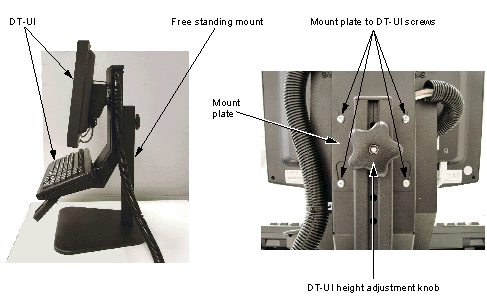
DT-CPU Installation
If the DT-CPU is mounted on a module, against a wall or on a wall bracket, make cable connections to the rear of the DT-CPU before installing it in the DT-CPU housing. Once the DT-CPU is installed in its mount, there may not be enough room behind the unit to access the connector panel.
Pay attention to shipped lengths, usable lengths and extension cable availability.
All cables are standard off-the-shelf cables with molded connector ends. If a cable is damaged, it must be replaced, not repaired.
The DT-UI cable is shipped as a complete assembly (cable bundle) and is already connected to the DT-UI. If optional equipment is installed and mounted on the DT-UI, its cable can be slipped into the cable bundle.
Card reader cabling is connected to the keyboard and hidden in the DT-UI display support bracket. If a card reader is added, cabling only needs to be routed through the display support bracket and cable bundle.
Route and dress cabling to promote security, personnel safety, and aesthetics.
 Never mount a DT-CPU with its front panel oriented upward. Mounting in this manner will restrict cooling air flow within the DT-CPU housing.

Do not attempt to install this equipment without assistance.

Never stack a DT-CPU under a CDM in an under the counter arrangement. The total weight will exceed the specified weight limitation for this arrangement. Always check the MedSelect product cut sheets for limitations.
 Do not install this equipment in a way that blocks access to the main power disconnecting means on the back of the DT-CPU. If the installation blocks access to the disconnecting means on the back of the DT-CPU, then you must provide an alternative disconnecting means such as an easily accessible power strip or you must ensure that the 120 volt outlet that the system is plugged into is nearby and easily accessible.
 This symbol is defined as: Consult documentation to find out the nature of the potential hazard and any actions to be taken.
Mounting the DT-CPU Housing
Refer to See Mounting On the Side of a Tower Module for additional tower component location.
Routing and connection information is described in See Connecting DT-CPU Cables.
The DT-CPU includes a metal housing, which provides a standard method of mounting the computer. Pre-drilled holes and threaded inserts on the bottom of the housing accommodate all of the mounting configurations.
The DT-CPU housing has a removable front cover to allow access to the computer. An opening at the rear allows access to the connector panel of the computer. The front panel is secured by two tabs and a lever. Allow two feet of cable slack to reach through the housing to make connections before installing the computer.
The outside holes on the bottom of the DT-CPU housing are only used in a hanging situation such as mounting on a wall. Use the four inside threaded inserts for mounting under a counter. Use the four slotted holes for stacking on top of a module. See DT-CPU Housing Bottom Panel Holes Usage is a reference for use of panel holes and threaded inserts in the housing bottom panel.
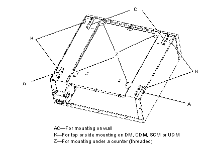
|
Security bit (19-038759-000K) for ¼” socket driver (an extension may be needed) |
Refer to your installation documentation, then proceed to the appropriate procedure for mounting the DT-CPU (see See DT Mounting Kits for required kit):
See Mounting on a DM, CDM, SCM or UDM
See Mounting With the Bottom of the Mount against a Wall (Vertical Orientation)
See Mounting on Top of a Tower Module
See Mounting On the Side of a Tower Module
Use this kit for mounting a DT-CPU on a DM, CDM, SCM, UDM or on a countertop or under a counter.
Mounting on a DM, CDM, SCM or UDM
The metal top of the DM, CDM, SCM, and UDM accommodates mounting of another module on top and also accommodates the DT-CPU housing. The keyholes (K in See DT-CPU Housing Bottom Panel Holes Usage) and locking pins on the bottom of the DT-CPU housing are used for mounting in this situation . The metal sides of the DM, SCM, and UDM accommodates mounting of the DT-CPU housing.
Kits and Parts
Also required for this mounting method is the following kit:
Procedure
To use this mounting method, perform the following steps:
Remove the six adhesive labels from the top surface to expose six holes on the module.
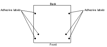
Mounting on a Countertop
The method of mounting a DT-CPU housing to the top of a counter is shown in See Mounting the DT-CPU Housing on a Counter.
Make sure there is clear access beneath the intended mounting location of the countertop. The supplied template has the same footprint as the DT-CPU housing. Follow the template directions to locate the four mounting holes on the countertop. The threaded inserts (Z in See DT-CPU Housing Bottom Panel Holes Usage) on the bottom of the DT-CPU housing are used for mounting in this orientation. Center punch each specified hole.
Account for cable routing to the computer when installed inside the DT-CPU housing. At least two feet of cable slack is needed to make connections to the computer before slipping it into the DT-CPU housing.
The drilled holes in the countertop will match the location of the four threaded inserts on the bottom of the DT-CPU housing. Check the template against the bottom of the DT-CPU housing to be sure that the correct hole locations have been selected on the template.
Use a 1/8” drill bit to make a starter hole first, and then a 5/16” bit for the final hole diameter, drill the four mounting holes completely through the countertop.
Depending on the cable routing, it may be necessary to drill a hole 2-1/2” diameter in the countertop to achieve a direct path to the DT-CPU.
Carefully position the DT-CPU housing on the countertop. The four threaded inserts on the bottom of the DT-CPU must line up with the four drilled holes in the countertop. The drilled holes in the countertop are large enough to allow some adjustment.
Thread the four supplied security screws and washers through the countertop and into the threaded inserts.
Do not over-tighten the screws because the inserts can break loose or strip.
Use the appropriate screw length for the counter thickness. Use additional washers to make up additional top thickness.
Install the computer into the DT-CPU housing as described in See DT Setup and Cabling.
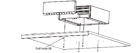
Mounting Under a Counter
The method of mounting a DT-CPU under a counter is shown in See Mounting the DT-CPU Housing under a Counter.
Be sure there is access above and below the mounting location of the countertop. The supplied template has the same footprint as the DT-CPU housing. Follow the template directions for locating the four mounting holes on the countertop. The outer holes (Z in See DT-CPU Housing Bottom Panel Holes Usage) on the bottom of the DT-CPU housing are used for mounting. Center punch each hole.
Account for cable routing to the computer when installed inside the DT-CPU housing. At least two feet of cable slack is needed to make connections to the computer before slipping it into the DT-CPU housing.
The drilled holes in the countertop will match the location of the holes on the bottom of the DT-CPU housing. Check the template against the bottom of the DT-CPU housing to be sure the correct hole locations have been selected on the template.
Use a 1/8” drill bit to make a starter hole first, and then a 3/8” bit for the final hole diameter, drill the four mounting holes completely through the countertop.
Depending on the cable routing, it may be necessary to drill a hole 2-1/2” diameter in the countertop to achieve a direct path to the DT-CPU.
With an assistant, position the DT-CPU housing, with bottom up, under the countertop. The DT-CPU housing panel holes must line up with the drilled countertop holes. The countertop holes are large enough to allow for adjustment.
If the countertop has a front edge with a lip or flange, you must place a shim between the bottom of the counter and DT-CPU housing to take up this space. A piece of plywood or additional washers (placed on all four mounting screws) may be used.
Thread the supplied carriage bolts through the countertop and bottom of DT-CPU housing (the housing is oriented bottom up in this configuration). Attach the nuts and washers to the bolts from inside the housing and tighten. Do not overtighten as the countertop can be deformed and damage may occur to the DT-CPU housing.
Use the appropriate screw length for the counter thickness.
Install the computer into the DT-CPU housing as described in See DT Setup and Cabling.
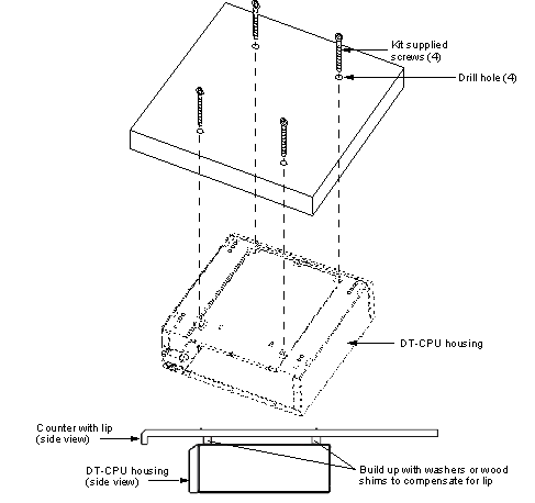
Mounting With the Bottom of the Mount against a Wall (Vertical Orientation)
When the DT-CPU housing is mounted with its bottom against a wall, no mounting bracket is required. The DT-CPU housing, however, is mounted with the same hardware type and manner as a bracket shelf.
The mounting holes on the bottom of the DT-CPU are located to match 16” (0.4 m) on center wall studding in a vertical orientation (see Product Cut Sheets for mounting orientations). Only four mounting holes are required in this situation.
Refer to the appropriate wall mounting instructions (for metal or wood studs) as described in the diagram (See DT-UI Channel to Stud Mounting and DT-CPU to Stud Mounting Diagram). The outer holes on the bottom of the DT-CPU housing are used for this type of mounting.
Account for cable routing to the computer when installed inside the DT-CPU housing. At least two feet of cable slack is needed to make connections to the DT-CPU before slipping it into the DT-CPU housing.
Use a 1/8” drill bit to make starter holes first and proceed for either metal or wood stud installation. Then using the required bit size (depending on metal or wood studding) for the final hole diameter, drill the four mounting holes.
With the help of an assistant, carefully position the DT-CPU housing bottom against the prepared wall. The four holes along the DT-CPU housing bottom must line up with the four drilled holes in the wall.
Attach the mounting hardware as described in the diagram (See DT-UI Channel to Stud Mounting and DT-CPU to Stud Mounting Diagram).
Install the computer into the mounted DT-CPU housing as described in See DT Setup and Cabling.
Mounting on Top of a Tower Module
Mount the DT-CPU to the large removable panel on top of the tower.
Remove the panel and attach the empty DT-CPU housing to it first, and then reinstall the panel. This sequence of installation is necessary to prevent structural damage to the panel. The DT-CPU housing will provide structural stability to the panel for the weight of the items that will be installed.
Review the procedures described in See DT Setup and Cabling for general information on computer installation. Then proceed as follows to install the DT-CPU on top of a tower:
Partially thread four of the provided 1-32 x 1/2” mounting screws into the DT-CPU housing from below. Leave approximately 2–3 mm (about 3/32”) between the screw head and the bottom of the DT-CPU.
Set the empty DT-CPU housing on top of large panel, matching the mounting screws to the corresponding keyholes in the top of the tower.
Once the four screws are within the keyholes, slide the DT-CPU housing forward until it is as far to the front of the tower as it will go.
To complete the installation, use a single #8 sheet metal screw to secure the DT-CPU housing to the top of the tower through one of the slots of the DT-CPU housing.
Mounting On the Side of a Tower Module
The DT-CPU and other components can be mounted on either side of a tower. The DT-CPU can also be mounted on the top. Refer to the Installation Worksheet for placement. Install components as shown using the holes on the side of the tower and following the cable routing guidelines described in See DT Setup and Cabling.
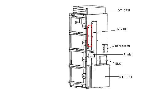
Multiple MedSelect Towers and Modules with IB Repeater
The tower has its own internal power supply and does not require a repeater to maintain the appropriate power level no matter the number of towers. However, the cable length and module count rules still apply for other MedSelect modules in the station, so that if the station has 100 feet of cable, a repeater is required.

Multiple SupplySelect Towers with IB Repeater and ELC
While no IB repeater is required when a DT is connected to a line of SupplySelect towers only, an IB repeater is required when an Electronic Lock Controller (ELC) is used. As illustrated in the figure below, the IB repeater is placed before the ELC.
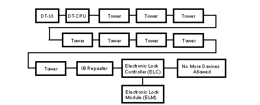
SupplySelect Dispensing Station.
For information about using IB repeaters, see See Station Orientation.
Secure the IB cables as described, but ensure there is enough slack for sliding one cabinet forward to change cabinet light bulb.
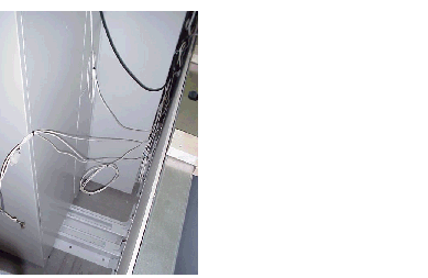
Mounting an ELC on a Wall, Counter or Module
The base of the ELC enclosure must be anchored to a surface with four screws or with Velcro when securing an ELC to a module. All mounting hardware is provided with the ELC for mounting to either a wood or drywall surface. The ELC enclosure consists of a removable metal top and a base that encloses and mounts the ELC CCA. The cover uses a restraining type hook-hinge that hooks to mating slots on the base.
ABTG recommends orienting the ELC so the hinges for the cover are at the bottom of the ELC when mounting the ELC to a vertical surface. This allows the cover to open from the top down against the hinge restraint. The cover hangs open, but remains attached to base. Other orientations require an opened cover to be held in hinge restraint. In this case, the cover should be removed and set aside during ELC internal access.
The ELC receives its operating power from the IB. Power outlet considerations are not applicable to this installation.
Refer to See Mounting On the Side of a Tower Module for additional tower component location.
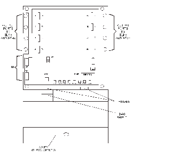
Cover opened.
Starter bits: 3/16” masonry bit for dry wall anchoring, 1/8” drill bit for wood screws
Bit for security screws (19-038759-000A)

Do not attempt to remove the Circuit Card Assembly (CCA) from the base. The CCA is held to the base by two corner screws, three corner self-clinching standoffs, and the heat sink screw for part U3. Heat sink attachment for U3 is not covered in this document.
Remove the security screw to open and remove the top cover of the ELC and set the cover aside.
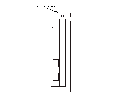
The base of the ELC has pre-drilled holes for mounting as shown in (See ELC Base Layout (Cover Removed)). If you are mounting on a vertical surface such as a wall, orient the hinge slots so they are facing down, and use the base as a template to mark hole locations. Use a level on the ELC before marking the holes. If you are mounting on a horizontal surface, no special considerations are needed for installation. Be sure to orient the ELC in the direction for the most direct route of cabling.
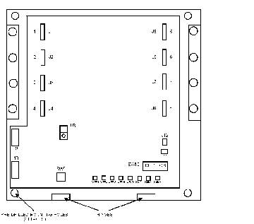
Drill the four starter mounting holes to accept the mounting hardware (3/16” masonry bit for dry wall anchors or 1/8” drill bit for wood screws).
Mount the ELC with the supplied hardware.
Attach all cabling, making sure that the locking tabs of the output cables are secured. The IB cable is supplied with the ELC. This cable is 4½’ (1.4m) long. A 20’ (6.1m) cable is available but not supplied. The output cables are supplied with the connected devices.
Use the two supplied tie straps to secure the attached IB cables to the ELC.
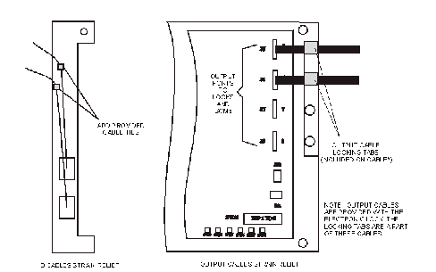
Be sure that the IB cables and ELC output cables are secured at the ELC enclosure where they connect with the CCA. The output cables have built-in locking tabs, but the IB cables must be secured by the supplied tie wraps.
Set the CCA DIP switches for type of device (ELM or SCM) connected to each output port.
The DIP switches have one-to-one correspondence with the ELC port positions. Therefore, DIP switch 1 is assigned to port 1 and switch 2 is assigned to port 2, etc. The “1” or ON position of a DIP switch identifies an ELM connection to the port. The “0” or OFF position of a DIP switch identifies an SCM connection to the port.
Do not replace the cover yet; it will be replaced after testing.
IB Repeater Installation
For information about using IB repeaters, see See Station Orientation.
This installation information applies to the MedSelect System and SupplySelect System. If you are installing a Centrack system, the procedure for mounting an IB hub is the same as the procedure for mounting a repeater. Read the information that follows, then follow the steps in Mounting an IB Repeater on a MedSelect Module below.
The IB repeater uses the installation kit shown in See DT Mounting Kits. Although the IB repeater does not need to be attached to a surface, mounting is recommended to prevent possible disruption of the system. This procedure is applicable to wall, counter, or any other surface installation. Specific installation information is provided for the SupplySelect System. It is not required to access the module internally for mounting purposes.
The IB repeater requires 115-vac power and has a line cords with standard 3-prong plugs. An power switch is provided, which must be accessible after installation.
If the IB repeater is not attached to anything, install all cables including the power cable as described in See Power and Cabling, and set the unit in place.
 The IB repeater must be powered off when connecting or disconnecting the IB cable and when connecting or disconnecting a module in the IB chain. Otherwise, damage to CCA circuitry can result. This is called “hot plugging” and should be avoided.
The IB repeater is mounted to a surface via a single bracket attached to the unit. The bracket is attached to the surface by three fasteners. There are two bracket attachment locations on the units that can be used. The bracket can be oriented in or out at these locations. Refer to Figure See IB Repeater; Preferred and Optional Positions for the various bracket orientations.
Refer to you installation documentation, then perform the appropriate procedure:
See Mounting an IB Repeater on a MedSelect Module
See Mounting an IB Repeater on a Tower Module
Mounting an IB Repeater on a MedSelect Module
Locate the IB repeater in an inconspicuous place with access to the power switch and connections. Refer to the installation planning documentation for installation details.
Locate the IB repeater within power cord reach of a power surge protected outlet.
See IB Repeater Surface Fasteners lists the fastening hardware for mounting the units on various surfaces.
Orient the supplied bracket attachment, if necessary.
Use the bracket as a template to trace out the three mounting holes. Drill out and size the holes in the mounting surface to accept the required fasteners.
Attach the unit to the surface with the fasteners determined by See IB Repeater Surface Fasteners.
Mounting an IB Repeater on a Tower Module
An IB repeater can be mounted on top of a tower in either of two positions. The preferred position is upright and lengthwise. The optional position is on its side and lengthwise. Both the preferred position and the optional position as well as cabling method are illustrated below.
Orient the supplied bracket attachment as shown in See IB Repeater; Preferred and Optional Positions and attach the unit to the surface with the supplied fasteners.

Refer to See Mounting On the Side of a Tower Module for additional tower component location.
Printer Installation
Orient the supplied bracket attachment as shown in See DT-CPU Housing and Other Components Mounted on the Side and attach the unit to the surface with the supplied fasteners.
The printer may also be mounted to any suitable surface by drilling holes and using the supplied bracket attachment and the supplied fasteners.
Refer to See Mounting On the Side of a Tower Module for additional tower component location.

Surge Protector Installation
Locate the surge protector in an inconspicuous location and secure it appropriately. For securing the surge protector to a tower module, use the Velcro supplied with the DT.
Optional Equipment Installation
Optional equipment used with this system is shipped with installation instructions, sometimes called Ship With documentation. Follow those instructions when installing any of the following options:
2D hand held scanner - wireless or tethered (SupplySelect and Centrack)
Station Orientation
The diagrams below illustrate the various equipment orientations for installations of MedSelect, SupplySelect or Centrack stations. The orientation has a direct bearing on the communication and power connection requirements.
Instructions for cabling the components are in the following topics:
See Installing the DT Cable Shield
MedSelect Dispensing Station without Tower Modules
A MedSelect dispensing station without a tower requires one IB repeater after every 100 feet of cable length or every 13 modules.
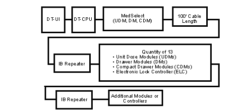
MedSelect Dispensing Station with Tower Modules
The tower has its own internal power supply and does not require a repeater to maintain the appropriate power level no matter the number of towers.
However, the cable length and module count rules still apply for other MedSelect modules in the station, so that if the station has 100 feet of cable, a repeater is required.
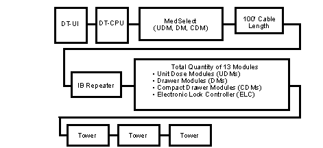
SupplySelect Dispensing Station with ELC
While no IB repeater is required when a DT is connected to a line of tower modules only, an IB repeater is required when an Electronic Lock Controller (ELC) is used. As illustrated in the figure below, the IB repeater is placed before the ELC.
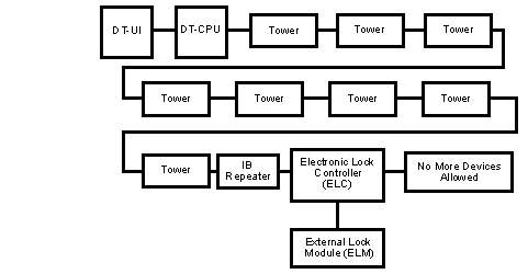
Power and Cabling
Power and IB cable connections are the same in final locations as they are in the staging area. To connect components, follow the instructions in See Connecting the Modules and See Supplying Power to the Dispensing Station.
After making the connections, finalize the cabling as described in the following topics in this chapter:
See Checking Service Loop Length
When routing cables between equipment at the installation, follow these guidelines:
Do not route cable runs across floors or where they could interfere with the normal working environment.
Use only vertical and horizontal runs.
Use cable ties and approved hangers for dressing cables over wall surfaces.
Use extensions only when absolutely necessary, and only use ABTG-specified cables.
Label cables to identify their purpose, origin, and destination. This assists service personnel if troubleshooting is required.
Wherever possible, cable runs should be inconspicuous, but still be accessible for maintenance.
Ensure that you create a two-foot service loop on each cable for bundling all cables. The extra cable allows you and other technicians to secure the cable yet have enough cable length to access the equipment. The cable bundle has a black plastic wire tie at the two-foot mark that enables you to locate the two-foot mark easily.
IB Cable Installation
At sites where the IB cable is routed through customer-installed conduit, manufactured “pullable” cabling is available in different lengths. This cable comes with one end terminated in pins and wrapped in heat shrink tubing to facilitate travel through conduit. The installer must insert these pins into the accompanying connector to complete the installation. No special tools are required. Be sure the contacts are secure in the connector body by lightly tugging on the wires.
The IB cable requires a D-Sub 9-pin connector and a 6-pin rectangular connector for terminating its ends. Refer to the connector pin information in See Six-Pin IB Cable Legend when attaching these connectors to the cable.
All cables have a part number tag for identification. Do not remove this tag because it may be needed when ordering a replacement.
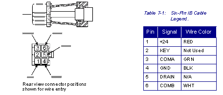
Securing Cabinet Cables
These guidelines apply to both MedSelect and SupplySelect cabinets.
Tie the power cords and cables and attach them to cabinet tie mounts.
Do not cable tie the power cable to the computer at this time: it must be contained within the two-foot service loop.
Loop and tie any cable slack greater than the two-foot service loop length.
Routing DT-UI Cables
When routing and tying down the DT-UI cable, be sure that enough free loop is present to permit a free and unbinding swing of an extended mount. Enough service loop must also be present to allow removal of the DT-UI (flush mount or extended mount) from its channel without disconnecting the cable bundle.
Refer to See Cable Bundle Routing Reference as a reference for routing and tying the DT-UI cable bundle and printer power cord. The optional cables should be inserted into the slit of the spiral wrap of the DT-UI bundle. Break out the cables from the bundle where required to make connections.
Insert optional cables into the slit of the spiral wrap of the cable bundle, adding several tie wraps along the length of the wrap to prevent the added cables from popping out.
Tie the optional equipment cables along side of the cable bundle.
Prior to securing the bundle, verify that the DT-UI on an extended mount has a full swing without binding by the cable bundle. Leave enough slack in the cable bundle to prevent this binding from occurring.
Tie the cable bundle and secure it to the rear of the cabinet with the tie mount.
Let the end of the cable bundle hang loose.
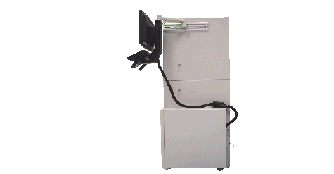
Connecting DT-CPU Cables
After completing the DT-UI cable routing, connect the cables of the DT-UI to the computer inside DT-CPU housing) and secure the cables in place. Follow the procedures for securing the cables to prevent strain on their connections to the computer or a possible disconnect. Power connections are not secured to their connectors and can work their way out until a disconnect occurs. The system will fail if this occurs.
All IB and power cables should already be connected and tied.
Make DT-UI cable connections to PORT cable harness.
Make the remaining connections (IB RS232, printer) to the rear of the computer. Be sure to tighten all thumb screws on connector housings.
Group all attached cables down the rear of the cabinet. Cable tie the RS232 cable from IB hub where shown.
Measure a two-foot service loop.
Tie up all cables connected to the computer. Make sure the cables without strain relief connectors are not pulling on their connectors.
Secure cables not running through cable housing. Follow the two-foot service loop.
Proceed to See Checking Service Loop Length.
Checking Service Loop Length
As a final check to make sure the service loop is of correct length, proceed as follows:
Do not disconnect cables. If they need to be disconnected to meet requirements, the service loop is too short. Remove tie wraps, lengthen the loop. Reinstall tie wraps.
Remove the front cover from the DT-CPU housing.
Pull the computer from the housing far enough to access its rear connectors.
The cable connections must have clear access. Assistance may be needed for this.
Installing the DT Cable Shield
The cable shield is a prefabricated metal piece that provides coverage for the cables and wiring coming from the DT-CPU housing at the back of a UDM. The shield has punched slots on its sides and is installed using the existing screws on the back of the UDM. The shield also has center slots to allow for cooling of the DT-CPU.
Perform this procedure only for installations in which the CPU rests on the UDM and only after all cables have been bundled and secured.
Loosen the eight screws on the back of the UDM, four on each side.
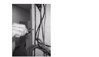
Initial Testing
If the installation plan calls for it, you may set up a display terminal (DT) in the staging area for two purposes: so that the database for the cabinets may be configured in the staging area, and to perform limited testing before moving the cabinets to their final locations. This may also be performed in the final location.
The cabinets need to be connected to each other and to the temporary DT with the appropriate IB cables and IB repeaters (refer to See Station Orientation).
The following steps to prepare the station and perform basic testing are described below:
DT Setup and Cabling
CPU, UPS, Computer, and Surge Protector
The DT-CPU housing may or may not be mounted in the staging area and is used to supply power to the other components (for an overview of DT components, see See Introduction, Introduction).
Follow the instructions below to assemble the DT in the staging area.
 Only connect the IB power supply, the monitor, and the computer to their designated outlets on the UPS as indicated in the accompanying documentation.
Remove the front of the housing by pulling its release lever forward and then lifting the front face:

Connect the internal electrical housing (IEH) cable at the rear of the PC.
Connect the PC USB to the UPS USB.

Connect the IB power to the UPS.
Connect the IEH power to the UPS.
Connect the UPS to the monitor.
Connect the IEH to a 110V outlet.

Connect the IEH to the module.

Centrack Systems Only
Connect the power cable from the IB hub to one of the three UPS Outlet plug-ins on the UPS (right side when viewed from rear). Do not connect to a surge plug-in.
Use either IB hub port to connect to a module.
The computer does not have a communication board. Connect the IB serial cable from the COM1 serial port on the computer to the DB9 serial port on the IB hub.
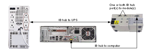
Connecting the Modules
Connecting Power Cables
Plug the module(s), tower, printer, DT-CPU, surge protector and other devices into the surge protector as indicated by the labels on the surge protector.
Connecting the IB Cables
Connect an IB cable to the IB port on the DT-CPU Housing.
If you are installing a Centrack station, connect an IB cable to one of the IB ports on the IB hub.
Connect the other end of the cable to one of the IB ports on the first module or ELC.
MedSelect and SupplySelect
Connect the IB cables in a MedSelect or SupplySelect system in this order:
Unit dose modules, drawer modules/compact drawer modules, towers, ELCs
IB Repeater if required followed by appropriate modules and ELM
The sequence of IB links between MedSelect and SupplySelect components is illustrated in See MedSelect Dispensing Station without Tower Modules, See MedSelect Dispensing Station with Tower Modules, and See SupplySelect Dispensing Station with ELC.
In a MedSelect/SupplySelect system, be sure to insert an IB repeater after every 13 modules or 100 single-strand feet of IB cable.
Centrack
Connect the IB cables in a Centrack system in this order:
Unit dose modules, drawer modules/compact drawer modules, towers, ELCs
IB Repeater if required followed by appropriate modules and ELM
Connect an IB cable to the other IB port on the component to which you just connected the input IB.
Connect the other end of the cable to an IB port on the next component.
Repeat steps 3 and step 4 until all components are connected in a serial connection chain (daisy chain) arrangement.
In a Centrack system, you can use one or both of the IB ports on the IB hub. If the module count or cable length requires the use of an IB repeater, using both outputs on the IB hub may eliminate the need for the IB repeater. In this case, you would create two serial connection chains: one for each output.
Supplying Power to the Dispensing Station
Connect the DT-CPU housing to the labeled receptacle on the provided surge protector with the included detachable power cable. The plug is located in the rear at the upper right of the DT-CPU housing.
Gather the Cable Bundle
Gather up the cable bundle coming from the DT-UI and bring it through the back of the DT-CPU housing.
Check whether the cables in the bundle are wire tied to the proper length. If not, use wire ties to secure each cable.
Connect the Remaining Devices
The remaining cable bundle is 15 feet in length and comes from the DT-UI. Note that around the cable bundle is a black plastic wire tie at the two-foot mark. This enables you to locate the two-foot mark and secure the bundle with the required service loop.
The connectors within this bundle are for the VGA output for the monitor, keyboard, and 12 volt power source for the monitor.
Gather each cable into a neat bundle and secure with a wire tie.
Ensure that enough cable remains at each end so that the computer and UPS can be removed later for service.
If you are connecting an optional printer, plug the printer’s cable into the parallel connection on the back of the computer, and then plug the printer’s power cord into the surge protector.
Plug In or Connect the Remaining Devices
Plug the VGA connector into the video out port on the computer. The pin configuration is unique and will prevent the video from being plugged into an incorrect port.
Plug the PS2 keyboard connector into the keyboard PS2 port on the back of the computer.
For Centrack systems, plug the PS2 mouse connector into the mouse PS2 port on the back of the computer.
As indicated on the keyboard cable, wire tie the cable to an adjacent cable that is secured through a connector, for example, the VGA connector cable.
Plug the single USB cable into any of the available USB ports located on the back of the computer.
Connect the 12-volt power bayonet style connector to the monitor power supply bayonet connector. The other end of the monitor power supply cable is already plugged into the UPS.
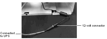
Plugging In the DT and Other Devices into the Surge Protector
A surge protector is provided with the DT. All external devices for the system must be plugged into the surge protector in their appropriate receptacles as indicated by the label for each receptacle on the surge protector. The surge protector should be located in an accessible area. For example, it could be mounted on the wall above the wall outlet to which it will be plugged or on the wall behind the DT-UI and below the keyboard.
Plug the DT-CPU into the labeled receptacle on the surge protector with the included detachable power cable. The plug is located in the rear at the upper right of the unit.
Display Terminal Software Setup
Proceed with these steps in order to prepare the DT and download the DT application from the server after performing the hardware installation.
Refer to See Calibrating and Troubleshooting, for adjusting touch screen properties, running the calibration program, rebooting the DT-CPU and establishing IB communications.
Calibrating the Touchscreen
Follow these steps to calibrate a touchscreen (Planar PT1510 mx series, Gunze driver):
Press the red “X” that appears for nine points on the screen.
Test the screen by touching all corners and sides of the monitor.
Assign IP and Router Addresses on the Display Terminal
All system computers must be assigned an IP address, and if the customer's site uses a router, the a router address must also be assigned. The customer or ABTG may provide the IP address. The customer must provide the router address.
Assign the IP and router addresses to a DT. You will need to know if the customer is using a router (or gateway) on the network to complete this task. Proceed as follows:

Press Ctrl+Esc to open the Windows Start menu.
Select Settings , Network Connections from the Start menu.
Select Local Area Connection .
Click Properties in the Local Area Connection Status dialog box.
Highlight Internet Protocol (TCP/IP) and click Properties .
Select Use the following IP address .
Enter the IP address provided by the customer in the IP Address field.
Enter the address provided by the customer in the Subnet Mask field.
If the customer uses a router (or gateway) on the network, then edit the Default Gateway field.
Editing the Host File
The host file is used to assign the IP address for the Database Server so the DTs can identify it. The IP address is unique to the MedSelect Database Server.
Obtain the IP address of the Database Server.
Press Ctrl+Esc to open the Windows Start menu.
Open Windows Explorer and then the etc driver directory:
From Start menu, select All Programs, Accessories, Windows Explorer .
Navigate to the C:\WINDOWS\system32\drivers\etc directory.
Open the Hosts file in that directory.
If the Open With dialog opens, select Notepad or WordPad .
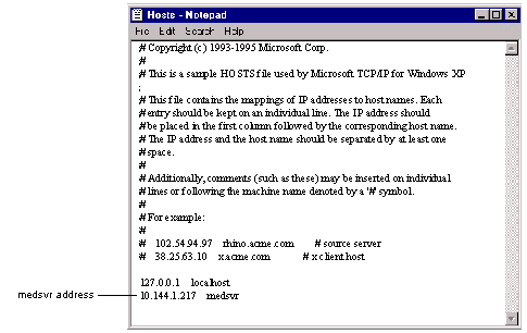
Change the medsvr address (in this case 10.144.1.217 ) to the server address obtained in See Obtain the IP address of the Database Server.. There is no need to edit the local host address.
Assigning a Computer Name (Node Name) to the Display Terminal
The computer name of the display terminal must match the display terminal node name that was given to the DT at the AWS (MedSelect System) or Control Center (SupplySelect System). The name can contain a hyphen or underscore, but cannot contain spaces or special characters. The name must be unique.
To assign a computer name (node name) to a display terminal, proceed as follows:
Press Ctrl+Esc to open the Windows Start menu.
Select Settings , Control Panel from the Start menu.
Select Performance and Maintenance.
Enter the node name in Computer description on the Computer Name tab.
Verifying the COM Port Settings
Follow the instructions in See RS485 Communication Board to ensure that the COM Port settings are correct.
Installing the Display Terminal Application
Use FTP to download the DT installation files from the server to the display terminal, then install the software.
Press Ctrl+Esc to open the Windows Start menu.
From the Start menu, select Run .
Type FTP medsvr, then click OK (or type another server name if it was changed from the as-shipped name of medsvr).
At the login prompt, enter iface .
Enter the iface password (must be supplied by the customer) at the password prompt.
Type lcd c:\temp at the FTP> prompt.
Type binary at the FTP> prompt.
Type prompt at the FTP> prompt.
Type one of the following at the FTP> prompt, and then press Enter :
For a DT at a MedSelect station:
mget /db/diskettes/dt/dtsetup/dtsetup.exe
For a DT at a SupplySelect Tower:
mget /db/diskettes/dtssp/dtsspsetup/dtsspsetup.exe
mget /db/diskettes/centrack/centracksetup.exe
At the next FTP> prompt, type quit.
Press Ctrl+Esc to open the Windows Start menu.
From the Start menu, select Run .
The display terminal application software will be installed. It is now ready to go on-line.
Press Ctrl+Esc to open the Windows Start menu.
The DT reboots and the login screen appears.
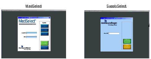
Dispensing Station Testing
If the dispensing station was not tested in the staging area, test it now.
Prior to moving any station(s), remove the DT side of all connections between the DT and all cabinets and tower modules. If you are installing more than one dispensing station, unplug the surge protector from the wall and leave the DT in place to stage the next dispensing station.
After the dispensing station has been completely installed, its basic functions should be tested and its components cleaned before it is turned over to the customer.
MedSelect Testing
Follow the instructions for loading the software as described in See Installing the Display Terminal Application.
Follow the instructions in the MedSelect Flex Service Manual for using the diagnostic utility, IBDiag, to open each drawer, rotate each coil and test each lock.
Cleanup
Storing or Returning the Temporary Floor Mounts
The temporary floor mount used for staging towers is not a customer purchased item but is provided for use in a staging area. After installation, temporary floor mounts are either returned to ABTG by an approved method or stored for use with additional towers. This is determined in the planning stages of the installation. Contact the project manager if you are uncertain as to what to do with the temporary floor mounts.
Removing Packing Material
No packing materials or supplies (excess cable ties, etc.) may be left in the staging area or permanent station locations unless otherwise arranged with the facility. Remove and dispose of all such materials.
Cleaning the Components
Every component in a new installation must be cleaned and in new condition when left with the customer. Follow the cleaning guidelines for each component below.
Monitor Screen or Touch Screen

Do not wipe the monitor screen or touch screen with soap, glass cleaner, or alcohol solution. Doing so may damage the antiglare coating and the touch screen components. Do not use paper towels or tissues. Doing so may scratch the glass.
To clean a monitor or touch screen, dampen a soft, clean, lint-free cloth with warm water and gently wipe the screen. Use another soft, clean, lint-free cloth to dry it.
Wipe the monitor frame with a soft cloth moistened with a 3 to 1 solution of warm water and dish washing detergent.
Keyboard

Do not use liquid or aerosol cleaners. These cleaners may contain flammable substances.
Use a vacuum cleaner with a brush attachment to remove dust from the keyboard.
Wipe the keyboard using a soft cloth moistened with a 3 to 1 solution of warm water and dish washing detergent.
Fingerprint Scanner
Depending on usage, the fingerprint scanner may need to be cleaned because the sensor window picks up dirt and grease from users’ fingers. Use a piece of 3M Scotch® MagicTM Tape or similar product against the sensor window surface to remove the dirt and grease. As an alternative, use a concentration of isopropyl alcohol of less than 50%.

Do not use paper towels or tissues when cleaning the fingerprint scanner. Doing so may scratch the sensor window. Do not use any heavy duty tape, such as, duct tape. Doing so may leave a sticky residue, defeating the purpose of cleaning the sensor window.
Using at least 2” in length, place a piece of 3M Scotch Magic Tape or similar product against the fingerprint scanner window surface. Place your thumb on the tape and rub the tape surface.
Lift the tape and check the window surface for cleanliness. If necessary, repeat the process with a new piece of tape until the window surface is clean.
Moisten a soft, clean cloth moistened with a solution of water and isopropyl alcohol with a concentration of less than 50% isopropyl alcohol.
Cabinet Sides and Doors

Do not use any abrasive soap when cleaning cabinet sides and doors. Abrasive cleaners may mar the finish.
Wipe cabinet sides and doors using a soft, clean cloth moistened with a 3 to 1 solution of warm water and dish washing detergent.
Cabinet Windows

Do not wipe the cabinet windows with any soap, glass cleaner, or alcohol solution.
Do not use paper towels or tissues on cabinet windows. Doing so may scratch the glass.
To clean cabinet windows, lightly dampen a soft, clean, lint-free cloth with warm water and gently wipe the window.
Tower Module Safety Label Removal
After the installation is complete, peel off the safety label from the top door window of all towers.
Non-optical Mouse
If your system has a non-optical mouse and the screen cursor skips or moves abnormally, you’ll need to clean the internal elements of the mouse.
Turn the retainer ring on the underside of the mouse counterclockwise, and then remove the ball.
Wipe the ball with a clean, lint-free cloth.
Blow carefully into the ball cage to dislodge dust and lint.
If the rollers inside the ball cage are dirty, clean the rollers with a cotton swab moistened lightly with isopropyl alcohol.
Re-center the rollers in their channels if they are misaligned. Ensure that residue from the swab is not left on the rollers.
Replace the ball and retainer ring. Then turn the retainer ring clockwise until it clicks into place.
Turnover
Paperwork
Serial number, configuration details, controller addresses, etc., are provided on the installation worksheet that is shipped with the equipment. The installation worksheet may have been physically attached to its equipment or included within the packaging.
Assemble all paperwork, including the installation worksheet and shipping document.
Verify that any changes to the original installation plan have been recorded on the installation worksheet.
Work with the customer to fill in the cabinet description on each installation worksheet. The description is the name given the cabinet by the customer.
Turn over the assembled paperwork to the person designated by the project manager (usually a hospital administrator).
Keys
Verify that all module and tower keys are present and grouped by dispensing station. Turn over all keys and key tags to the person designated by the project manager. It is the customer’s responsibility to make sure the provided key tags identify the keys in a way that is meaningful to the customer.
If a key becomes separated from its tag, the customer can usually identify the key by comparing the number imprinted on the key with the number imprinted on the cabinet lock, but not all locks have easily visible numbers. In some cases, a mirror and flashlight can be used to view the number; in other cases, the lock must be removed from the cabinet to see the number stamped on the side of the cylinder. It is important for the customer to maintain a list of key identifiers at the time of installation, making it easy to identify the key later.
The installation worksheets identify the key and lock number for each component. The customer should keep a list of keys in a vault or other safe place so that replacement keys can be easily manufactured in the future, should the need occur.
This chapter contains additional details about some components of the MedSelect, SupplySelect and Centrack systems. While not all of this information may be required for your installation, it may help provide additional understanding of the components. The components covered here are:
See Uninterruptible Power Supply (DT-CPU UPS)
See Display Terminal Housing (DT-CPU Housing)
See Uninterruptible Power Supply (Centrack UPS)
See Display Terminal User Interface (DT-UI)
See Electronic Lock Controller (ELC)
See Inventory Bus (IB) Repeater
See Inventory Bus (IB) Hub - Centrack
See Accessing the System Properties and Device Manager
Display Terminal (DT)
The DT is the computer system that controls access to the modules and towers in a dispensing station. In a MedSelect station, the DT supplies power the modules. Each DT has a DT CPU and a DT user interface:
Display Terminal CPU
Computer (DT-CPU Computer)
The DT-CPU computer is a Hewlett-Packard 5700 with a 2.13 GHz Intel® Core™2 Duo processor and 2 GB of RAM. This computer is powered on and off by a button on the front that must be pressed and held until the unit turns on or off. The front of the DT-CPU has two USB ports, a DVD-RW drive, and jacks for a microphone and headphone.
The back of the DT-CPU provides PS/2 mouse and keyboard ports, a parallel (25-pin) printer port, a serial port (9-pin) connector, four (4) USB ports, an RJ-45 network port, a VGA connector for the DT-UI monitor, and a power cord connector.
The computer also has an internal IB communication board with preset DIP switches (not present in Centrack systems).
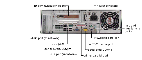
Uninterruptible Power Supply (DT-CPU UPS)
The uninterruptible power supply (UPS) includes a battery to maintain power in the event of a power outage. The UPS keeps the computer and other devices running for several minutes after a power outage, facilitating a controlled computer shutdown.
At the front of the UPS is an on/off button and a reset button for the signal that notifies you of a possible power failure.

Display Terminal Housing (DT-CPU Housing)
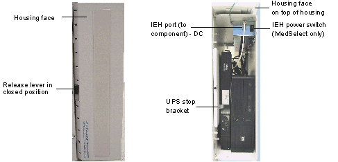
Internal Electrical Housing
Within the DT-CPU Housing is an internal electrical housing (IEH). The internal electrical housing provides the connection for power and communication to the DT-UI. In addition to the power outlet for the UPS, the IEH also provides an on/off switch that allows the IB communication board to be powered off without requiring you to pull the plug from the surge protector outlet. Other elements within the DT housing are the power supply for the monitor and the IB communication cable.
The MedSelect DT-CPU internal electrical housing has a switch in the front and a power receptacle in the back. A product label with a check mark confirms this power supply. The label is located on the inside of the DT-CPU housing.
The SupplySelect tower has a power source. There is a receptacle but no switch on the internal electrical housing. The product label, without a check mark, indicates that a power supply is not provided. The product label is on the inside of the DT housing.
Uninterruptible Power Supply (Centrack UPS)
The uninterruptible power supply (UPS) includes a battery to maintain power in the event of a power outage. The UPS keeps the computer and other devices running for several minutes after a power outage, facilitating a controlled computer shutdown.
At the front of the UPS is an on/off button and a reset button for the signal that notifies you of a possible power failure. Three power outlets for components are available on the right side when viewed from the rear.
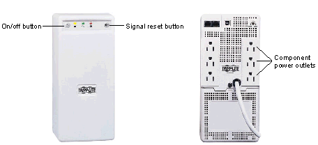
Display Terminal User Interface (DT-UI)
This is the monitor and keyboard that the clinician uses to request access to the cabinets. The user interface may also include any of the following optional devices:
2D hand held scanner - wireless or tethered (SupplySelect and Centrack)
Electronic Lock Controller (ELC)
If the system has an External Lock Module or a MedSelect Standard Cabinet Module, it needs an ELC to control those locks.

Inventory Bus (IB) Repeater
This section provides information on acceptable station configurations, including the use of IB repeaters. These differences arise because different setups are required to maintain the power supply to the components that make up the station.
The purpose of an IB repeater
As an electric or communication signal travels across a cable, the signal weakens and distorts. In general, a repeater is an electronic device that continuously monitors the signals on each cable. When a repeater senses a signal on one cable, it transmits an amplified copy on the other cable so that the signal maintains its strength.
The IB repeater does not monitor, but it provides an acceptable signal, where needed, for stations consisting of several or distant dispensing components.

Inventory Bus (IB) Hub - Centrack
When modules are used with Centrack software, an IB hub is required to distribute the IB signal and power from the CT.

Mounting Components on a Tower (TM)
The DT-CPU, DT-UI, IB repeater or hub, printer, and ELC may be mounted on other modules. The tower provides mounting capability for all the components.
Components can be mounted on either side of a tower. The DT-CPU can also be mounted on the top. Refer to the Installation Worksheet for placement. Install components as shown in the graphic below using the holes on the side of the tower and following the cable routing guidelines described in See DT Setup and Cabling.
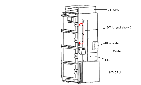
RS485 Communication Board
During manufacturing, the RS485 communication board should be set properly. However, if the board is removed and reinstalled, the communication settings must be changed from the defaults. In the procedures that follow, you’ll close the DT and the IBDiag applications. Then, you’ll open the Control Panel and move through the selections to the Device Manager window. Within Device Manager, you’ll change the PCI, FIFO, and Data Rate settings. Once you’ve changed those settings, you’ll update the DT initialization file, DT.INI, by changing the IB port setting to 3.
Accessing the System Properties and Device Manager
Close the DT and IBDiag applications if they are running.
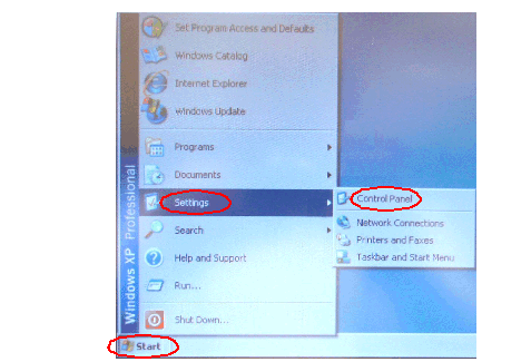
Select System within the Control Panel .
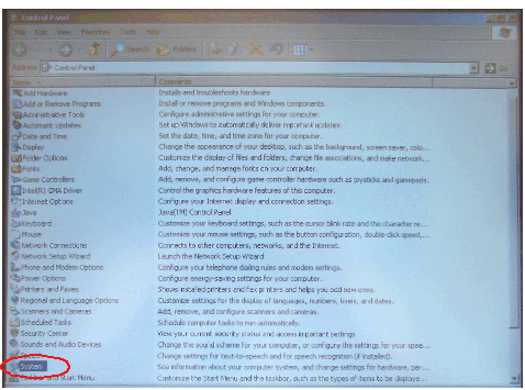
Select the Hardware tab in the System Properties window.
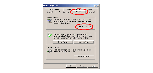
Double-click (COM & LPT) in the Device Manager window.
Double-click Enhanced Communications Port (COM3) .
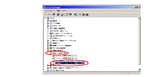
Changing Hardware Configuration Settings
Select the Settings tab in the Enhanced Communications Port Properties window.
Select RS422/485 to accommodate the RS485 internal IB communication board.
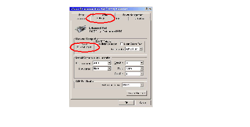
Changing Flow Control
The FIFO buffers are set to transmit at 4 and receive at 100. Flow control thresholds are set to 16 and 112.
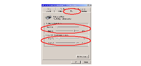
Modifying the DT.INI file
For the MedSelect DT
The DT.INI file is located on the C:\ drive within the DT folder. The file opens with Notepad or another text editing application.
Open the Windows Explorer application on the desktop.
Search for and open the DT.INI file.
Remember that the display terminal application should be closed.
The port setting assignment is located at the top of the file. Change the setting to 3.
[IB]
port = 3
For the SupplySelect DT
The DTSSP.INI file is located on the C:\ drive within the DTSST folder. The file opens with Notepad or another text editing application.
Open the Windows Explorer application on the desktop.
Search for and open the DTSSP.INI file.
Remember that the display terminal application should be closed.
The port setting assignment is located at the top of the file. Change the setting to 3.
[IB]
port = 3
Module and Tower Circuit Card Assembly (CCA)
System Controller Addresses
The controller chip on each controller CCA is labeled with a unique 8-digit controller address (an AD/SN address). This address is assigned by the chip manufacturer and is unique among all manufactured chips. The system uses the address to uniquely identify the controller for communication purposes. Therefore, if a controller chip is replaced, its new address must be swapped with the old one at the Administrative WorkStation (MedSelect System) or Control Center (SupplySelect System). Also, all CCAs are clearly identified on the CCA component side by name, revision, top assembly part number, and schematic diagram number.
A listing of controller addresses for devices in the system (as of publication date of this manual) is provided in See Controller Address Types. The first two digits of the controller address indicate which MedSelect Systems component is associated with the controller.
Calibrating the Gunze® Planar Touch Screen
The touch screen should be calibrated before turning the station over to the customer and may need to be calibrated later if the system is not responding properly or not at all to the touch. Before calibrating the touch screen for the first time only, you must adjust the touchscreen properties to use the appropriate controller.
Adjusting Touch Screen Properties
Perform this procedure only once, when the monitor is first installed.
Open the touchscreen properties windows as follows:
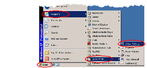
Installation Troubleshooting
Rebooting the DT-CPU
If the DT-CPU locks and requires rebooting, try a soft reboot through the Windows Security application first. Execute a hard reboot only if the soft reboot fails.
A hard reboot should be done through the UPS only, not the DT-CPU.
A soft or hard reboot also cycles the IB communication board, IB hub, or IB module, depending on the system equipment and orientation.
Soft Reboot of the DT-CPU
Simultaneously press the Ctrl+Alt+Del keys to access the Windows Security application.
In the Windows Security window, press Shut Down
In the Shut Down Windows window, press Restart and press OK.
Do not select Shut down in this step.
The DT-CPU begins the reboot process, cycling the CPU and other devices (IB communication board or IB module). Cycling the CPU shuts down and restarts all devices connected to or installed with the DT-CPU.
If you accidentally pressed Shut Down and then clicked OK , restart the computer by pressing its power button.
Establishing IB Communications
If the DT cannot find the module nodes, the DIP switches may be set incorrectly on the RS485 IB communication board inside the computer. Check the DIP switches as follows:
Disconnect surge protector from the wall outlet.
Disconnect all cables from the back of the DT-CPU computer.
Slide the computer out of the DT-CPU housing.
Remove the RS485 IB communication board from the computer.
Verify that the DIP switches are set as shown in See DIP Switches.
The following describes mounting requirements to handle equipment that is being relocated. Where part numbers are listed, they should be made available through the service parts program or the project manager.
For module-mounted modules (UDM, CDM, SCM, DT-CPU, DT-UI), counter-mounted modules (UDM, CDM, SCM, DT-CPU), wall-mounted components without use of a bracket (e.g. DT-CPU):
If the installation planner has decided that the existing kits cannot be reused, the appropriate mounting kit can be ordered.
For other components (Printer, ELM, ELC):
The existing mounting hardware should be reused. If this is not possible, contact ABTG Customer Support for further options.
Index
C
moving to a permanent location 53
cable - IB 55, 63, 65, 85, 138
system controller addresses 173
compliance, OSHPD 56, 57, 92, 94
D
installation worksheet 13, 16, 55, 85
disconnecting in staging area 155
S
horizontal divider (SCM) 23, 25
single item access (SIA) drawers 27
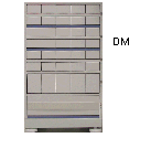 :
:  :
:  :
: 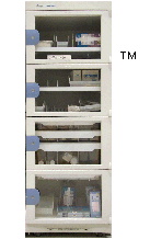 :
:  :
: 
