®

High Capacity UDM Solids Dispenser Double
Position Installation Guide
June 2002
TM-MEDDBL-000B PD 4190
For use when
configuring a UDM solids dispensing
position to be a double dispensing position
Document History
|
Document
Number
|
Date
|
Remarks
|
|
TM-MEDDBL-000A
TM-MEDDBL-000B
|
11/30/98
6/06/2002
|
First
Printing
Insert
MedSelect company name & logo
Update
Patents, Trademarks and Copyright
|
Copyright protection is claimed for
each revision listed in the document history, as of the date indicated.
The following are registered
trademarks of MedSelect Inc. and cannot be used without the written permission
of MedSelect Inc.: MedSelect®, MedSelect Systems®,
MedSelect SmartStock®, and Selectrac®.
The
following are trademarks of MedSelect Inc. and cannot be used without the
written permission of MedSelect Inc.:
MedSelect™,
MedSelect Systems™, MedSelect Administrative WorkStation (AWS)™,
MedSelect Centrack™, MedSelect Display Terminal (DT)™, MedSelect Examiner™,
MedSelect Interface Engine™, MedSelect MedOrders™,
MedSelect Nursing WorkStation (NWS) ™, MedSelect SmartStock™,
Selectrac™, SupplySource™, SupplySource
Configure-It™, and SupplySource Control Center™.
Other
brand and product names are trademarks or registered trademarks of their
respective companies.
This
document contains proprietary information.
If the document pages state the information is confidential (or words of
similar import), then this document is intended solely for the use of the
copyright owner's employees or other personnel expressly authorized in writing
by the copyright owner. Other uses of
this information without the express written consent of the copyright owner
have not been authorized. This document
should be treated as confidential material for security reasons.
The information contained in
this document is subject to change without notice. When using the document for system
implementation, please call your authorized sales or service representative for
any applicable changes.
In no event shall the
copyright owner or its suppliers be liable for any special, indirect, or
consequential damages of any nature resulting from the use of information in
this manual.
No part of this document may
be reproduced, stored in a retrieval system, or transmitted, in any form or by
any means: electronic, mechanical, photocopying, recording, or otherwise,
without prior written permission from the copyright owner.
Priced Item
Use of the MedSelect and
SupplySource Systems, as well as all aspects of patient care, must still rely
upon the professional skill and judgment of a competent medical professional, who
should independently verify the accuracy and completeness of all
pharmacological, medical, legal, or similar information entered into the system
and the results obtained therefrom.
MedSelect products or
their operation are covered by one or more of the following US patents: 5404384, 5533079, 5790409, 5848593, 5912818,
5957372, 5961036, 5971593, 5993046, 6019249, 6073834, 6108588, 6112502,
6141942, 6163737.
Other MedSelect patents pending: 09/014076, 09/086857,
09/288685, 09/384650, 09/428035, 09/428036, 09/578540, 09/848633, 09/849625,
09/921014.
Contents
1. Installing the UDM Double
Dispense Position Upgrade Kit............................................................ 1
1.1 Description............................................................................................................................................................................. 1
1.2 Tools
Required...................................................................................................................................................................... 1
1.3 Reference
Documentation.................................................................................................................................................... 1
1.4
Configuration Evaluation..................................................................................................................................................... 2
1.5 Description
of Shelf Indicator Points................................................................................................................................. 2
1.6 Combining
Adjacent Oral Dispensing Positions.............................................................................................................. 3
1.6.1
Configuration Setup For SHDP Style 1...................................................................................................................... 4
1.6.2
Configuration Setup For SHDP Style 2...................................................................................................................... 5
1.6.3
Configuration Setup For DHDP................................................................................................................................... 7
This kit is used to modify a Unit Dose Module Solids
Dispenser shelf to allow it to dispense medications wider than allowed with the
standard position. The purpose of the
kit is to combine adjacent positions and have them operate as a single unit. The kit may support capacities of 12, 18, or
24 items per helix. Refer to Table 1 for
a list of the kit’s contents.
NOTE
Please refer to hospital service
procedures and guidelines as stated in the Service and Installation Guide.
Table 1
Contents of the Double Dispense Position Upgrade Kit
|
Kit Number 19-040180
|
|
|
-000A
|
-000B
|
-000C
|
DESCRIPTION
|
|
|
1
|
|
|
24 Capacity Helix, Right Hand
|
|
|
1
|
|
|
24 Capacity Helix, Left Hand (yellow)
|
|
|
|
1
|
|
18 Capacity Helix, Right Hand
|
|
|
|
1
|
|
18 Capacity Helix, Left Hand (yellow)
|
|
|
|
|
1
|
12 Capacity Helix, Right Hand
|
|
|
|
|
1
|
12 Capacity Helix, Left Hand (yellow)
|
|
|
2
|
2
|
2
|
Connector Jumper
|
|
|
2
|
2
|
2
|
Helix Guide
|
|
|
1
|
1
|
1
|
Double Position Permanent Divider
|
|
|
1
|
1
|
1
|
Retainer Clamp Bracket
|
|
|
1
|
1
|
1
|
#6 x .25 Self Tapping Screw
|
|
|
|
|
|
|
|
|
The following tools are needed to perform this upgrade.
1.
#2 Phillips Head Screwdriver
2.
#1 Phillips Head Screwdriver (used only to reposition
the motor and the index switch to the large
1.4” OD helix position)
3.
Needle nose pliers
The reference documentation associated with this kit is
listed in Table 2.
Table 2
Reference Documentation
|
Description
|
Part No.
|
|
Installation Guide
|
TM-MEDINS-000A
|
|
Service Guide
|
TM-MEDSVC-000A
|
This kit allows two adjacent solids dispense positions to be
combined into a single dispense unit.
Use Table 3 to determine the appropriate setup. The examples that follow
use the last two positions.
Table 3
Configuration Setup Information
|
Configuration Style
|
Med Width (in)
|
Med Width (mm)
|
|
SHDP Style 1
|
1.5”-1.8”
|
38mm-46mm
|
|
SHDP Style 2
|
1.8”-2.5”
|
46mm-63mm
|
|
DHDP
|
2.3”-3.0”
|
58mm-76mm
|
The Solids Dispenser Shelf is labeled with indicator points
that show the mounting location of the single and double permanent dividers and
plastic length guides. Figure 1 defines
these points.
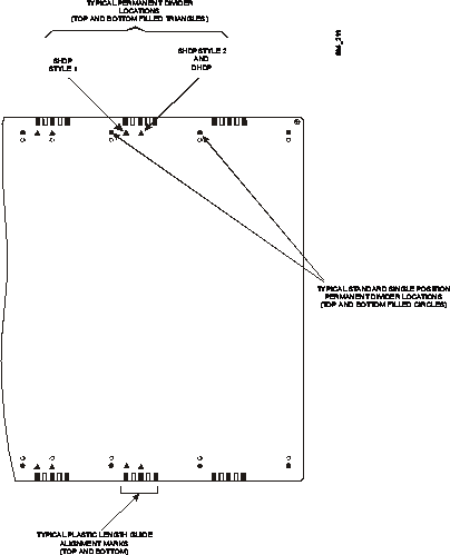
Figure 1
Solids Dispenser Shelf Indicator Points
Figure 2 shows the parts that you should be familiar with
when upgrading a single dispensing position. As previously mentioned, the last
two positions are used as an example.
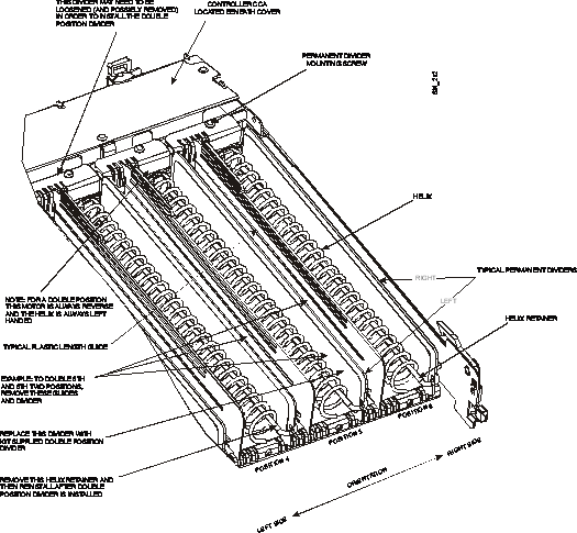
Figure 2
Factory Installed Standard Solids Dispensing Position
It is necessary to remove Permanent Dividers from the
combined positions. The adjacent left
position always requires a kit-supplied Double Position Permanent Divider. The drive motors of the two combined
positions do not need to be unmounted unless they are
mounted in the low or 1.0” helix diameter position. All
combined positions use the 1.4” OD helix.
NOTE
In the following text, the two adjacent dispense positions
are referenced as left and right as observed from the top and front of the
shelf (see Figure 2 for orientation).
Proceed as follows to combine two adjacent positions, then proceed to the desired specific configuration setup
(SHDP Style 1, SHDP Style 2, or DHDP):
NOTE
The Helix for both the left and right positions are removed
for all setup configurations.
1.
Remove the Helix Retainers from the Permanent Dividers
associated with the double position Additionally,
remove the helix retainer from the position immediately to the left of the dual
position location (if present). The retainer is usually tight and requires some
force to remove.
2.
Remove the Plastic Length Guides from the two
positions. This is accomplished by grasping the top rear tab, and then lifting
this end straight up. The front of the divider is hooked into a front slot of
the shelf.
3.
Remove the existing Helix from the left and right
positions (5th and 6th positions of this example).
4.
Remove the Permanent Divider from between the two
positions. The Helix Retainer was previously removed in Step 1. The divider is
secured in place by a phillips
head screw at the rear of the position.
The front of the divider is hooked into a front slot of the shelf
base.
5.
Remove any Helix Guides that may be used in the two
positions. Depending on the setup configuration, these guides may be used
again. However, guides are included with
the kit.
6.
Make sure that both motors are mounted in the high
position to accommodate the 1.4 diameter helix.
7.
Reverse the direction of rotation of the left position
(5th position in this example) drive motor by connecting its cable to the
reverse motor polarity socket on the controller CCA. The controller CCA provides
forward and reverse drive sockets for each drive motor. For example, the CCA socket J1 is used for
the forward direction, and J2 is used for reverse.
NOTE
The left side drive motor is always configured for
counterclockwise rotation with a left hand wound helix. This forces the med packages against the left
permanent divider rather than the less sturdy plastic length guide. The left
position motor is used to drive the meds since it is nearer to the center of
the double positions.
Follow these steps to set up a Single Helix, Double Position
configuration to support meds that are no wider than 1.8 inches:
1.
Install the kit provided Double Position Permanent
Divider using the left mounting hole in the divider (see Figure 3 for
orientation). The divider replaces the
left adjacent position (5th position in this example) divider previously
removed. The divider hooks into the
front slot first. Filled in triangles
are provided on the label to assist in aligning up the ends of the
divider. Align the divider over the
right-most colored triangles of the right position and at each end of the
position. The divider is forced over these triangles when mounted correctly
using the left mounting hole.


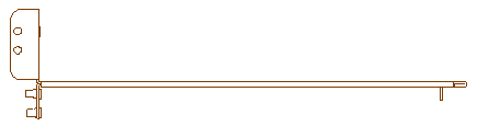
Figure 3
Permanent Divider Mounting Holes
2.
Replace the left Helix (just removed) with a left hand
wound Helix as provided with the kit.
This Helix has a yellow color code.
3.
Insert the Helix Retainer. The top set of holes are
for the 1.4" diameter helix.
4.
Install the helix and divider jumpers onto the
controller CCA above the right dispense position motor (6th position in this
example) and above the previously removed right Permanent Divider.
5.
Install the Plastic Length Guide to the right of the
yellow Helix, setting it to the appropriate med width, by hooking the front into
the base and then snapping in the back tab.
6.
Use the CCA test buttons to manually test the position
so that the index point is established.
Adjust the Plastic Length Guide as necessary.
Follow these steps to set up a Single Helix, Double Position
configuration to support meds that are between 1.8 and 2.5 inches wide:
1.
Attach the Retainer Clamp Bracket to the kit supplied
Double Position Permanent Divider using the #6 x .25 Self Tapping Screw. Note: the alignment post on the divider goes
through the Retainer Clamp Bracket (see Figure 4).


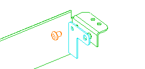
Figure 4
Attaching a Retainer Clamp Bracket to the Double Position
Permanent Divider
2.
Position the Helix Guide as shown in Figure 5. Loosen the Permanent Divider on the right and
slip the Helix Guide under it. The Helix
Guide aligns
with a slot in the divider.

Figure 5
Positioning the Helix Guide
3.
Install the kit supplied Double Position Permanent
Divider (with Retainer Clamp Bracket attached) using the right mounting hole in
the divider (see Figure 3 for orientation).
The divider replaces the left adjacent position (5th position in this
example) divider previously removed. The
divider hooks into the front slot first.
Filled in triangles are provided on the label to assist in aligning up
the ends of the divider. Align the
divider over the left-most colored triangles at each end of the position. The
divider is placed over these triangles when mounted correctly using the right
mounting hole.
4.
Replace the left Helix (just removed) with a left hand
wound Helix as provided with the kit.
This Helix has a yellow color code.
5.
Install the helix and divider jumpers onto the
controller CCA above the right dispense position motor (6th position in this
example) and above the previously removed right Permanent Divider.
6.
Install the Plastic Length Guide to the right of the
yellow Helix, setting it to the appropriate med width, by hooking the front
into the base and then snapping in the back tab.
7.
Use the CCA test buttons to manually test the position
so that the index point is established.
Adjust the Plastic Length Guide as necessary.
Follow these steps to set up a Double Helix, Double Position
configuration to support meds that are between 2.3 and 3.0 inches wide:
1.
Install the kit provided Double Position Permanent
Divider using the left mounting hole in the divider (see Figure 3). The divider replaces the left adjacent
position (5th position in this example) divider previously removed. The divider hooks into the front slot
first. Filled in triangles are provided
on the label to assist in aligning up the ends of the divider. Align the divider over the right-most colored
triangles at each end of the position. The divider is placed over these
triangles when mounted correctly using the left mounting hole.
2.
Replace the left Helix (just removed) with a left hand
wound Helix as provided with the kit.
This helix has a yellow color code.
3.
Replace the right Helix with the kit supplied right
hand wound Helix.
4.
Install one Permanent Divider Jumper above the
previously removed center Permanent Divider.
This jumper installation indicates to the system that both motors must
be driven simultaneously.
5.
Insert all Helix Retainers. The top set of holes are
for the 1.4" diameter helix.
6.
Use the CCA test buttons to manually test the position
so that the index point is established.